Quick connect guide for the floppy, Arduino, and PSU.
.
.
.
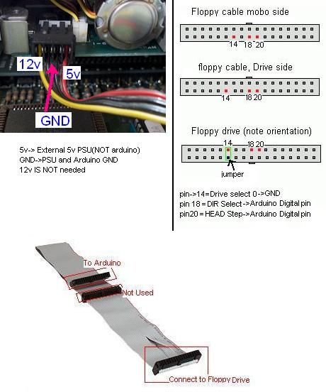
Rather than waste PSU floppy conenctors, i just took some solid core wire and parallel connected 5v and GND from each floppy drive, then used a jumper(see pic) for drive select, and connected the step(pin 20) and direction(pin 18) to the Arduino. Furthermore, contrary to "popular" belief, only five connections are required on each floppy drive. 12v(Yellow) is not required, and pin 1 of the floppy cable doesn't need to be grounded.
The following are the only required connections for each floppy drive:
Pin 14->GND this can be done by simply putting one of those IDE HDD 2 pin jumpers between pin 14 and a nearby GND pin on the floppy drives data port.
Pin 18->Arduino digital pin
Pin 20-> Arduino digital pin
5v(Red) to External 5v PSU
GND(either black wire) to Arduino AND external PSU GND
8 floppy setup:

Video of my results:
Really cool!
ReplyDeleteI'm also trying to do this. How do you manage the direction change of the head?
im at school right now, and all the schemes i drew for the pinout are at home. ill get you them later :).
ReplyDeletehttp://www.interfacebus.com/PC_Floppy_Drive_PinOut.html is the floppy interface pinout.
ReplyDeletei used the arduino like:
floppy cable 1:
arduino digital 2-- Step control floppy pin 20
arduino digital 3-- Direction floppy pin 18
floppy cable 2:
arduino digital 4-- Step control floppy pin 20
arduino digital 5-- Direction floppy pin 18
and so on for floppy 3, 4 etc
then on each cable i had a floppy at the last connector with:
pin 1 GND
pin 10 Motor enable ->GND
pin 14 Drive Select 0 ->GND
Make sure you get the floppy pinout correct, as i was reading it wrong and thus using the wrong pins-many hours of frustration...
as i didn't make the code posted here all i can say is hook it up like i said, and follow the github info.
Have Fun!
Hello,
ReplyDeletedo I have to connect ground more than once or are the 17 GND pins connected to each other?
The problem was that the motor was always spinning, no matter what was connected.
I'm currently at work and as soon as I get home, i will try that.
nope just the pins i said, all GNDs are internally connected(or maybe they aren't; i don't know, but i know they don't all need to be connected)
ReplyDeleteOk. I measured the resistance and they are connected. Good so far.
ReplyDeleteWhat's not good is that the motor keeps spinning no matter what I do. I plugged the audio output in /STEP and 5V in /MOTORENABLE. I also tried not to use /MOTORENABLE.
How can I make the motor stop while there is no tone?
hmm i dunno, they are reverse in terms of on and off(0 is on(GND), 1 is off(5V)). try messing around with the wiring, other than that i don't know.
ReplyDeleteare you using the interrupt moppy code? is it working for you, as it didn't for me...
I'm actually using my own code made by me from scratch. And I treat motors like speakers. Can you show me your code, please?
ReplyDeleteok hold on my motors do you mean the little steppers, or the larger motor tat turns the actual floppy disk?
ReplyDeleteafter you send the signal to the motor with tone, do you have a noTone(spkr pin here) before the next tone you play?
I mean the head motor, not the turn table. And I usualy do noTone().
ReplyDeleteI just received my "real" power supply so there's no need for crocodile clips and a transformator.
Now the floppy drive turns the floppy for half a second and then does nothing.
hmm, i remember having that before. i think it was something to do with the pinout(when i was looking at the connector upside down :D)
ReplyDeletecheck your pinout to my previous post, and then its probably your code.
look at the last 3 or so posts here: http://arduino.cc/forum/index.php/topic,74232.0.html
they have 2 examples on how to just move the stepper head, not music or anything, but a good diagnostic.
I uploaded what I understood from the pinout:
ReplyDeletehttp://xload.dev-ch.de/ae4b675be745f708/screen384.jpg
I know that the line with one pin missing must be GND (I measured that).
So whatever I plug in or not, it simply doesn't step. It seems to initialize tho. The table spins for a sec and then the floppy drive does nothing :/
What pins exactly do I have to connect to? Currently I'm connecting 5V to 10 and 14 and audio signal to 20 and one pin to GND. Sadly it doesn't work
http://arduino.cc/forum/index.php/topic,74232.msg563016.html#msg563016
ReplyDeleteOkay, got it so far as that the LED is on now. So I've plugged in /ENABLE correctly. I've plugged the audio output in 20 and it doesn't make pretty music, umh...
ReplyDeleteHere is my desk, btw :)
http://xload.dev-ch.de/2beccd3c802cc3b3/screen385.jpg
So I tried the example from the post (connections and the code from there) and it does also nothing else than turn on the LED.
cleaner than my desk at times:)
ReplyDelete1. you only have 3 wires going to the floppy(missing pin 1 GND, its needed, it didnt work without it for me).
2. do you have arduino, floppy, and psu grounds all shared?
3. your floppy cable is backwards, the twist should be at the floppy end(in this case it doesn't matter though, but still)
4. i dunno whats going on with that breadboard there, but you can just hook the wires directly to the arduino.
ok so do this:
-bring out 2 digital pins(3 and 6), and a ground from the arduino(make sure PSU is sharing GND).
-look at your floppy cable+connect like this to the breadboard according to prev step↑: http://dl.dropbox.com/u/28052258/fddr.gif
-use code from here: http://arduino.cc/forum/index.php/topic,74232.msg563040.html#msg563040
I forgot to share GND. But that also doesn't help. I connected the Arduino GND to one of the black cables of the PSU and the floppy ground - yet no difference. I also got the pins right and my other floppy drive behaves identical.
ReplyDeletei don't know. go to the forum for help, as im out of ideas.
ReplyDeleteOk, but thanks for the help. Thanks to you I'm much further now :)
ReplyDeleteThis comment has been removed by the author.
ReplyDeleteupdated the post with more info
ReplyDeleteAgain, I must thank you for your work here! After I've successfully done it back then, Your post helped me connecting the pins on the drive side. Otherwise I wouldn't know that pin 14 on the cable side is in fact pin 12 on the drive side!
ReplyDeleteHere is my video: http://www.youtube.com/watch?v=EQfa118c1Js
I'm currently working on a machine with 40 floppy drives and already managed dual channel play :)
Also I suggest you try vibrating the head instead of moving. It is far louder and cleaner :)
Have a nice day!
Hey Guys! I got one floppy disk connected to the arduino and it worked heavenly great! But once I wanted to connect the second one, I got it all wrong! Can someone illuminate me about the connections of the second and third floppy with a nice scheme or pic?? Thank you so much!!
ReplyDelete