Friday, March 30, 2012
RC Car Update 2
Before i dive in; for anyone that doesn't know what this is: This is a cheap RC car that i bought from Walmart. I am putting a Arduino and a Windows Phone on it so that i can control it wirelessly from my computer. A C# program on the computer will receive video from the phone over WiFi and send arrow key "events" to the phone which will then tell the Arduino via Bluetooth to go forward/back etc. I am currently working on getting the Windows phone to send video to the computer, but i found that the phone doesn't have a Bluetooth API, so i cant develop with Bluetooth to send commands to the Arduino from the phone.
While swirling ideas around in my head about how to get around this, i came up with this: A photo resistor senses how much light is reaching it, right? In the same way i am sending video to the computer from the phone, i can send data to the phone. So, if i place a photo resistor, or two, flush with the screen of the phone, and change the color that is displayed on the screen. The photo resistors will sense the brightness level and know the difference between the black and white screen. I tried this out with my Arduino, and it worked great! I didn't even have to use drastic color changes like white and black for it to work. I pulled up an image on the screen of the phone that had black, red, and orange squares and the Arduino had three distinct values from the photo resistor as i moved the photo resistor around to the different colors!
In the end it should work like this: if i press the up arrow key on my keyboard, a portion of the phone screen turns white; the Arduino will read the value of the photo resistor and if it finds the value from the photo resistor to be within the set threshold for white, it will trigger the RC car forward button!
LED Chaser; 555N and CD4017BE
I've had a few 555's on hand for a while, but i just recently found a CD4017BE, which allows me to finally make my LED chaser. So, the 555 timer sets an output pin HIGH and LOW based on the period and duty cycle set by two resistors and a cap. The CD4017 will "count" each time its clock pin is brought HIGH after being low; this clock pin is the 555 output. Lets say the 4017 is reset and is starting from the beginning:
1. The 555 output is brought HIGH
2. The 4017 turns the first output pin to HIGH(the LED turns on).
3. Then the 555 goes LOW( the first output on the 4017 is still HIGH).
4. Next, the 555 output is HIGH again.
5. The 4017 sets output one LOW and sets output two HIGH.
6. Repeat until output 10, then restart at 1 again.
As it counts from one to ten, the ten output pins are also turned on and off. Each time clock pin is brought HIGH, it turns off the previous output and turns on the next. When it reaches "10" in its count and then the 555 output is HIGH again, the 4017 will restart at the first output pin.
Pic:

Video:
Saturday, March 24, 2012
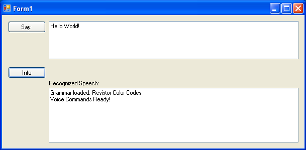
Resistor Color Codes with Speech Recognition.
As I was cleaning(ish) my work area, i noticed how annoying it is having to look up resistor codes. I thought it would be fun to do a voice recognition program in C# with the SAPI, the Microsoft Speech API, to help me. I have successful been able to speak resistor color codes, and get a value in ohms, or k ohms etc, spoken back by the computer. Its OK, but the recognition is pretty sketchy, and probably requires more time to get the words precise enough than it takes to use a standard resistor code calculator. I'm still trying to find a way to recognize all types of numbers so that i can do a value to color code conversion too.
Binary: WindowsFormsApplication1.exe. Source: WindowsFormsApplication.ZIP There is a info button that tells you what you have to say, but only the "five band value" and "four band value" commands work currently.

Additionally, i have been doing some windows phone developing. I have to say, windows phone is a pretty good phone from a end user stand point(lots of good features, UI). But from a developer standpoint, its missing a LOT of functions that would be very helpful in making apps( ex some FM radio stuff, the entire Bluetooth function). TCPIP.zip is the source for a simple TCPIP program that sends messages between the phone and a computer on the same LAN network.
Both of these programs are in no way 100% done, but i will eventually fix them all up and make them more usable :)
Binary: WindowsFormsApplication1.exe. Source: WindowsFormsApplication.ZIP There is a info button that tells you what you have to say, but only the "five band value" and "four band value" commands work currently.
Additionally, i have been doing some windows phone developing. I have to say, windows phone is a pretty good phone from a end user stand point(lots of good features, UI). But from a developer standpoint, its missing a LOT of functions that would be very helpful in making apps( ex some FM radio stuff, the entire Bluetooth function). TCPIP.zip is the source for a simple TCPIP program that sends messages between the phone and a computer on the same LAN network.
Both of these programs are in no way 100% done, but i will eventually fix them all up and make them more usable :)
Friday, March 23, 2012
Rock, Paper, Scissors, Java!
I thought id try out Java as it is widely used in high school, college, and my favorite reason; Android development! I've already done some limited C# stuff, so, as other people have said, its a easy transition. I'm currently using the Netbeans IDE, and most likely will stick with it. So far by biggest "complaint" has been typing 'System.out.println("stuff"")' every time i want to print something to console. Visual Studio, which is where I do C# code, has way better auto complete and can learn fairly quickly what is typed a lot in console programs: Console.Writeline("stuff");. Don't get me wrong, Nebeans does have auto complete, just not to the extent of C#, and putting the most used code to the top of the pop up list.
I found this awesome site which starts at the basics(not because i need to start at the basics :P), but so that i can find the differences between C# and Java. They had a simple switch statement that had a random input of one to three and was used as an example for guessing Rock, Paper, or Scissors (RPS). For some reason this got stuck in my head, so I made a console RPS game. RockPaperScissors.jar file Source: RockPaperScissors.zip You can open the .jar file on any computer that has Java installed (i guarantee you every computer does :)) with this command in the command prompt(windows) or terminal(osx): java -jar /path/to/jarfile.jar

I found this awesome site which starts at the basics(not because i need to start at the basics :P), but so that i can find the differences between C# and Java. They had a simple switch statement that had a random input of one to three and was used as an example for guessing Rock, Paper, or Scissors (RPS). For some reason this got stuck in my head, so I made a console RPS game. RockPaperScissors.jar file Source: RockPaperScissors.zip You can open the .jar file on any computer that has Java installed (i guarantee you every computer does :)) with this command in the command prompt(windows) or terminal(osx): java -jar /path/to/jarfile.jar

Sunday, March 18, 2012
Blinkn' LEDs with NPNs
I'm trying to learn more about the hardware side of electronics. So, after sorting my collection of parts with ecDB, I created a blinking LED circuit with a NPN. Scheme below. I found, obviously, that when i changed the values of the caps/resistors, the time each LED was on and how long between each on period changed.
I believe that i understand what is happening, but i am not exactly sure:
1. The first cap is charged, which causes the second NPN to allow current to flow.
2. That completes the circuit on the second LED and charges the second cap.
3. Now the first cap is depleted, but the second cap is charged, so the first NPN and LED turn on.
4. The second cap is discharging and the first cap is now charging.
5. Repeat.

 |
| They are blinking, but the camera doesn't have a fast enough shutter time to detect it. |
R2R Button Resistor Ladder
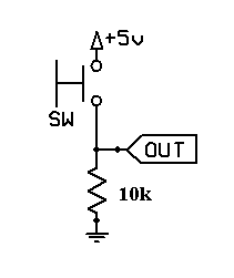
I'm sure everyone has encountered that time when you use all your digital ports for other things, but then you also need a button. It is possible to use a analog port as a digital port (pinMode(A0,Input/Output);), or you can use a few resistors and have a whole bunch of buttons(4+ easily) on one analog port.
Basically, this is how it works: A 10k resistor pulls the analog pin low, then each button is connected to the analog pin, and a resistor of some value to Vcc on the button. Each buttons resistor value is different so that Arduino can tell which button has been pressed. I found it best to use odd values values starting at 300ohm. Ex 300ohm, 500, 700, ..., 1.1k, 1.3. That way, if two buttons are pressed at once the resulting value is different than any of the buttons being pressed individually. Or you could use 1k, 3k, 5k... etc. The main thing is to make sure two buttons don't equal another button when pressed.

#define AnalogBtnPin A0
int AnalogBtn =0;
int Button1Cnt =0;
int Button2Cnt =0;
int Button3Cnt =0;
int Button4Cnt =0;
int Button5Cnt =0;
void setup()
{
// put your setup code here, to run once:
Serial.begin(115200);
}
void loop() {
// put your main code here, to run repeatedly:
AnalogBtn = analogRead(AnalogBtnPin);
Serial.println( AnalogBtn);
if(AnalogBtn >= 508 && AnalogBtn <= 510)
{
Button1Cnt +=1;
Serial.print("Button 1 pressed "); Serial.print(Button1Cnt); Serial.println(" times.");
}
if(AnalogBtn >= 888 && AnalogBtn <= 890)
{
Button2Cnt +=1;
Serial.print("Button 2 pressed "); Serial.print(Button2Cnt); Serial.println(" times.");
}
if(AnalogBtn >= 970 && AnalogBtn <= 972)
{
Button3Cnt +=1;
Serial.print("Button 3 pressed "); Serial.print(Button3Cnt); Serial.println(" times.");
}
if(AnalogBtn >= 1003 && AnalogBtn <= 1005)
{
Button4Cnt +=1;
Serial.print("Button 4 pressed "); Serial.print(Button4Cnt); Serial.println(" times.");
}
if(AnalogBtn >= 1014 && AnalogBtn <= 1016)
{
Button5Cnt +=1;
Serial.print("Button 5 pressed "); Serial.print(Button5Cnt); Serial.println(" times.");
}
}
Note: you will have to find the correct thresholds for your resistors.
Basically, this is how it works: A 10k resistor pulls the analog pin low, then each button is connected to the analog pin, and a resistor of some value to Vcc on the button. Each buttons resistor value is different so that Arduino can tell which button has been pressed. I found it best to use odd values values starting at 300ohm. Ex 300ohm, 500, 700, ..., 1.1k, 1.3. That way, if two buttons are pressed at once the resulting value is different than any of the buttons being pressed individually. Or you could use 1k, 3k, 5k... etc. The main thing is to make sure two buttons don't equal another button when pressed.

Made with Fritzing
Code:#define AnalogBtnPin A0
int AnalogBtn =0;
int Button1Cnt =0;
int Button2Cnt =0;
int Button3Cnt =0;
int Button4Cnt =0;
int Button5Cnt =0;
void setup()
{
// put your setup code here, to run once:
Serial.begin(115200);
}
void loop() {
// put your main code here, to run repeatedly:
AnalogBtn = analogRead(AnalogBtnPin);
Serial.println( AnalogBtn);
if(AnalogBtn >= 508 && AnalogBtn <= 510)
{
Button1Cnt +=1;
Serial.print("Button 1 pressed "); Serial.print(Button1Cnt); Serial.println(" times.");
}
if(AnalogBtn >= 888 && AnalogBtn <= 890)
{
Button2Cnt +=1;
Serial.print("Button 2 pressed "); Serial.print(Button2Cnt); Serial.println(" times.");
}
if(AnalogBtn >= 970 && AnalogBtn <= 972)
{
Button3Cnt +=1;
Serial.print("Button 3 pressed "); Serial.print(Button3Cnt); Serial.println(" times.");
}
if(AnalogBtn >= 1003 && AnalogBtn <= 1005)
{
Button4Cnt +=1;
Serial.print("Button 4 pressed "); Serial.print(Button4Cnt); Serial.println(" times.");
}
if(AnalogBtn >= 1014 && AnalogBtn <= 1016)
{
Button5Cnt +=1;
Serial.print("Button 5 pressed "); Serial.print(Button5Cnt); Serial.println(" times.");
}
}
Friday, March 16, 2012
First 555 Timer Project
As the title says, this is my first time using 555 timers :). I have three timers on the breadboard, each is hooked up to a color of a RGB LED.They all have a about 50% duty cycle, but are set for different pulse lengths so that it blends the colors randomly-ish. The 555 requires two resistors and a capacitor to set the duty cycle and pulse length. I could, but id rather not, do the calculations for finding which cap/resistors to use, so i found this program which does it automatically.
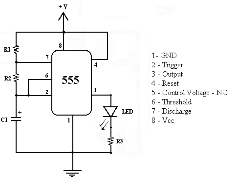
The following is the basic 555 scheme i used to build off of. R1, R2 and C1 change the pulse and duty cycle. R3 is the current limiting for the LED. Also; the 555 can source or sink a max of 200ma.
Scheme:
Pics:
 |
| The resistor and cap calculator |
 |
| Don't mind those NPNs/PNPs in the center; they're from a different project |
Wednesday, March 14, 2012
Arduino Software and Hardware Based Button Debouncing
This, button debouncing, is vital for using any type of button with the Arduino. A bounce is referring to when the switch is pressed, and since its mechanical, its not a clean one time press. There are a whole bunch of tiny connections between the two sides of the switch before the button is actually pressed fully, and so the Arduino incorrectly counts those tiny connections as presses. So, to fix this we need to debounce the switch and make those tiny connections not count as button presses. There are two ways to do this; through software, and with hardware.
 Software based debouncing is by far the most common and easier to implement depending on where your skills are(HW vs SW). Basically, the Arduino runs in a loop(like it normally does) and when it detects the switch as "HIGH" it records the time. then it checks again, and if its still "HIGH" and its been high for long enough to be considered a full press of the switch, it sets a value or something saying that a button was completely pressed. Here is a ton of different ways to do software debouncing. This is some code from the Arduino website that works perfectly:
Software Debouncing:
const int buttonPin = 2; // the number of the pushbutton pin
const int ledPin = 13; // the number of the LED pin
// Variables will change:
int ledState = HIGH; // the current state of the output pin
int buttonState; // the current reading from the input pin
int lastButtonState = LOW; // the previous reading from the input pin
// the following variables are long's because the time, measured in miliseconds,
// will quickly become a bigger number than can be stored in an int.
long lastDebounceTime = 0; // the last time the output pin was toggled
long debounceDelay = 50; // the debounce time; increase if the output flickers
void setup() {
pinMode(buttonPin, INPUT);
pinMode(ledPin, OUTPUT);
}
void loop() {
// read the state of the switch into a local variable:
int reading = digitalRead(buttonPin);
// check to see if you just pressed the button
// (i.e. the input went from LOW to HIGH), and you've waited
// long enough since the last press to ignore any noise:
// If the switch changed, due to noise or pressing:
if (reading != lastButtonState) {
// reset the debouncing timer
lastDebounceTime = millis();
}
if ((millis() - lastDebounceTime) > debounceDelay) {
// whatever the reading is at, it's been there for longer
// than the debounce delay, so take it as the actual current state:
buttonState = reading;
}
// set the LED using the state of the button:
digitalWrite(ledPin, buttonState);
// save the reading. Next time through the loop,
// it'll be the lastButtonState:
lastButtonState = reading;
}
Hardware Debouncing:

This, on the other hand is used much less. The big point here is that it uses a 100nf cap. This cap is charged as soon as the circuit gets power and since the cap is fully charged there is no current flowing and the pin will read LOW. As soon as the button is pressed, the cap is discharged and the pin will read HIGH. Using this method, all that is needed for code is a simple digitalRead to check the status of the button.
This, on the other hand is used much less. The big point here is that it uses a 100nf cap. This cap is charged as soon as the circuit gets power and since the cap is fully charged there is no current flowing and the pin will read LOW. As soon as the button is pressed, the cap is discharged and the pin will read HIGH. Using this method, all that is needed for code is a simple digitalRead to check the status of the button.
#define buttonPin 2 // the number of the pushbutton pin
#define ledPin 13 // the number of the LED pin
void setup() {
pinMode(buttonPin, INPUT);
pinMode(ledPin, OUTPUT);
}
void loop() {
digitalWrite(ledPin, digitalRead(buttonPin)); //sets the LED to current state of button
}
#define ledPin 13 // the number of the LED pin
void setup() {
pinMode(buttonPin, INPUT);
pinMode(ledPin, OUTPUT);
}
void loop() {
digitalWrite(ledPin, digitalRead(buttonPin)); //sets the LED to current state of button
}
Arduino + LM298
Tonight, I used some LM298s that i got from Sparkfun(the bare IC, not the overpriced prebuilt version) to drive the same hobby motor as i did yesterday. The setup is different, obviously, compared to the ULN2803, but still pretty simple. Mainly, it requires 4 diodes instead of 2 like i put on the ULN2803, but thats only because the LM2803 has built-in direction control, whereas i was just doing one direction with the ULN2003. I saw a noticeable change in the PWM quality of the LM298s compared to the ULN2803; its definitely a lot smoother.
One thing that i had to figure out was how to control the thing... it has, as you can see, two inputs, two outputs and an enable pin for each of the two motors it can drive. Output 1/2 or 3/4 go to the motor, input 1/2 or 3/4 go to the Arduino along with a enable A/B pin (A is for motor 1 with input 1/2 and output 1/2). The two input pins can be regular digital pins as they just control the polarity of the motor(flip it to go in reverse). The Enable pin actually triggers on/off the motor and needs to be a PWM digital pin so that the Arduino can change the speed of the motor. Also, the Lm298 has a internal voltage drop of about 1.5v, so a 5v motor voltage worked great for the probably 3v(?) motor.
Scheme:

#define EnA 3 //enable A Pin
#define In1 6 //Input 1
#define In2 7 //input 2
void setup()
{
pinMode(EnA, OUTPUT);
pinMode(In1, OUTPUT);
pinMode(In2, OUTPUT);
}
void loop()
{
//rev speed up
for(int i = 0; i<255; i++)
{
//rev
digitalWrite(In1, LOW); //set dir
digitalWrite(In2, HIGH); //set dir
analogWrite(EnA, i); //enable mtr, half speed reverse
delay(20);
}
delay(1000); //full speed for 1 sec
//slow down
for(int i = 255; i>0; i--)
{
//rev
digitalWrite(In1, LOW); //set dir
digitalWrite(In2, HIGH); //set dir
analogWrite(EnA, i); //enable mtr, half speed reverse
delay(20);
}
//fwd speed up
for(int i = 0; i<255; i++)
{
//fwd
digitalWrite(In1, HIGH); //set dir
digitalWrite(In2, LOW); //set dir
analogWrite(EnA, i); //enable mtr, half speed fwd
delay(20);
}
delay(1000); //stay full speed for 1 sec
//slow down
for(int i = 255; i>0; i--)
{
//fwd
digitalWrite(In1, HIGH); //set dir
digitalWrite(In2, LOW); //set dir
analogWrite(EnA, i); //enable mtr, half speed fwd
delay(20);
}
//'stop'
digitalWrite(EnA, 0); //not enabled
delay(500);
}
One thing that i had to figure out was how to control the thing... it has, as you can see, two inputs, two outputs and an enable pin for each of the two motors it can drive. Output 1/2 or 3/4 go to the motor, input 1/2 or 3/4 go to the Arduino along with a enable A/B pin (A is for motor 1 with input 1/2 and output 1/2). The two input pins can be regular digital pins as they just control the polarity of the motor(flip it to go in reverse). The Enable pin actually triggers on/off the motor and needs to be a PWM digital pin so that the Arduino can change the speed of the motor. Also, the Lm298 has a internal voltage drop of about 1.5v, so a 5v motor voltage worked great for the probably 3v(?) motor.
Scheme:

Code:
#define EnA 3 //enable A Pin
#define In1 6 //Input 1
#define In2 7 //input 2
void setup()
{
pinMode(EnA, OUTPUT);
pinMode(In1, OUTPUT);
pinMode(In2, OUTPUT);
}
void loop()
{
//rev speed up
for(int i = 0; i<255; i++)
{
//rev
digitalWrite(In1, LOW); //set dir
digitalWrite(In2, HIGH); //set dir
analogWrite(EnA, i); //enable mtr, half speed reverse
delay(20);
}
delay(1000); //full speed for 1 sec
//slow down
for(int i = 255; i>0; i--)
{
//rev
digitalWrite(In1, LOW); //set dir
digitalWrite(In2, HIGH); //set dir
analogWrite(EnA, i); //enable mtr, half speed reverse
delay(20);
}
//fwd speed up
for(int i = 0; i<255; i++)
{
//fwd
digitalWrite(In1, HIGH); //set dir
digitalWrite(In2, LOW); //set dir
analogWrite(EnA, i); //enable mtr, half speed fwd
delay(20);
}
delay(1000); //stay full speed for 1 sec
//slow down
for(int i = 255; i>0; i--)
{
//fwd
digitalWrite(In1, HIGH); //set dir
digitalWrite(In2, LOW); //set dir
analogWrite(EnA, i); //enable mtr, half speed fwd
delay(20);
}
//'stop'
digitalWrite(EnA, 0); //not enabled
delay(500);
}
Pics:
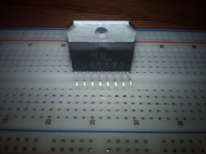 |
| Pins bent to .1 spacing over center of breadboard |
 |
| All setup + running |
 |
| Diodes are hiding out behind the motor... |
Video:
Tuesday, March 13, 2012
Arduino + ULN2803
I got some ULN2803 NPN darlington arrays working with my Arduino. Its quite simple to setup, not much different than a NPN transistor. As you can see from the scheme below, i used the ULN2803 as a PWM for a motor and for a RGB LED strip. Code wise, its just simple analogWrite to change the PWM, or a digitalWrite.
The left side of the picture below shows the setup for a simple hobby motor @ 3v and about 825ma(V=IR, I=3.3/~4ohm) each darlington in the array can do about 500ma, so i just tied three together, and now i can use up to about 1.5A. I used the code(also below) to go back and forth, full to slow speed, with PWM and analogWrite on the Arduino.
The right side shows how i set it up for some RGB LED strips. They are 12v, common anode(+), and so i just fed it 12v on the "+" pin and connected each of the R, G, and B cathode(-) pins to darlington on the ULN2803. Again, works great with analogWrite.

 |
| Motor Setup |
 |
| LED setup with motor left overs |
RGB Code
#define DelayTime 10 //time between colors
#define FadeDelay 10 //time to spend on each PWM level
void setup()
{
// put your setup code here, to run once:
pinMode(5, OUTPUT);
pinMode(3, OUTPUT);
pinMode(6, OUTPUT);
}
void loop()
{
//red
digitalWrite(5, HIGH);
for(int x= 255; x>1; x--)
{
analogWrite(5,x);
delay(FadeDelay);
}
delay(DelayTime);
digitalWrite(5, LOW);
//blue
digitalWrite(3, HIGH);
for(int x= 255; x>0; x--)
{
analogWrite(3,x);
delay(FadeDelay);
}
delay(DelayTime);
digitalWrite(3, LOW);
//white
digitalWrite(5, HIGH);
digitalWrite(3, HIGH);
digitalWrite(6, HIGH);
for(int x= 255; x>1; x--)
{
analogWrite(5,x);
analogWrite(3,x);
analogWrite(6,x);
delay(FadeDelay);
}
delay(DelayTime);
digitalWrite(5, LOW);
digitalWrite(3, LOW);
digitalWrite(6, LOW);
}
Motor Code
#define delaytime 50
void setup() {
pinMode(3, OUTPUT);
digitalWrite(3,LOW);
delay(250);
}
void loop() {
for(int i =0; i<255; i++) //slow to fast
{
analogWrite(3, i);
delay(delaytime);
}
delay(500); //full speed for .5sec
for(int i =255; i>0; i--) //fast to slow
{
analogWrite(3, i);
delay(delaytime);
}
}
Thursday, March 8, 2012
Arduino Controlled RC Car: Update
Moving towards my goal of a WiFi controlled and camera feedback RC car, I have successfully controlled the car over Bluetooth with the "arrow keys". This is basically how it went:
A processing app reads the arrow keys and connects to the arduino bluetooth module using the internal computer Bluetooth. I put in a little parsing code for the serial output too: <1,0,0,0> the "<" and ">" represent the beginning and end of the datastream being sent. Boolean on/off logic is being used to determine which button is pressed. Think of it as; <fwd state, rev state, right state, left state> I also put in some safety checks so that forward and backward buttons can't both be on at once. The arduino the reads that data, splits it into individual values for forward, back, right, and left. Then I created a quick function that takes the split values and sets the buttons on the car remote to them(they are 0 or 1, low or high). So, then the remote sends the commands to the car and off it goes.
My final goal is to use a smartphone on the car that sends a live video feed back to the computer, and sends commands received over WiFi from the computer to the Arduino (the bluetooth sends the commands to the Arduino from the phone).
This code doesn't have to be used with Bluetooth; just connect your Arduino and tell processing to send the data to the Arduino serial port.
Pics:


Processing Code
import processing.serial.*;
Serial myPort; // Create object from Serial class
int[] KeyArray = new int[4];
int PrtChose = 6; //number of the serial port, starts at 0
PFont f; //initailize a font
void setup() {
size(200, 300);
noStroke();
background(0);
f = loadFont("ComicSansMS-48.vlw"); //Load Font
textFont(f, 15); //Specify font type
print(Serial.list());
String[] Avail = Serial.list();
for(int i =0; i < Avail.length; i++)
{
text(Avail[i], 10, 20*i+80); //print text of avaliable serial ports to app
}
fill(0,255,0);
text(Avail[PrtChose], 10, 20*PrtChose+80); //highlite the port in use
String portName = Serial.list()[PrtChose];
myPort = new Serial(this, portName, 115200);
}
void draw()
{
//chnage colors of 4 ellipses according to what keys are pressed
if (KeyArray[0] == 1)
{
fill(0, 255, 0);
}
else
{
fill(255, 0, 0);
}
ellipse(100, 20, 5, 5);
if (KeyArray[1] == 1)
{
fill(0, 255, 0);
}
else
{
fill(255, 0, 0);
}
ellipse(100, 40, 5, 5);
if (KeyArray[2] == 1)
{
fill(0, 255, 0);
}
else
{
fill(255, 0, 0);
}
ellipse(120, 40, 5, 5);
if (KeyArray[3] == 1)
{
fill(0, 255, 0);
}
else
{
fill(255, 0, 0);
}
ellipse(80, 40, 5, 5);
}
void keyReleased() //key released
{
if (key == 'w') //fwd, fwd has been let up, so set stop fwd message
{
KeyArray[0] = 0; //no longer pressed
}
if (key == 's') //down
{
KeyArray[1] = 0;
}
if (key == 'd') //right
{
KeyArray[2] = 0;
}
if (key == 'a') //left
{
KeyArray[3] = 0;
}
writeMsg(); //send updated state over serial
}
void keyPressed() //key pressed
{
if (key == 'w') //fwd
{
KeyArray[0] = 1; //fwd key pressed down, set forward command
}
if (key == 's') //down
{
KeyArray[1] = 1;
}
if (key == 'd') //right
{
KeyArray[2] = 1;
}
if (key == 'a') //left
{
KeyArray[3] = 1;
}
writeMsg();
}
void writeMsg()
{
//so both fwd/back, lft/rght dont activate at same time
if(KeyArray[0] == 1 && KeyArray[1] == 1)
{
KeyArray[0] = 0;
KeyArray[1] = 0;
}
if(KeyArray[2] == 1 && KeyArray[3] == 1)
{
KeyArray[2] = 0;
KeyArray[3] = 0;
}
//<0,0,0,0> <fwd,bck,rght,Lft>
myPort.write("<" + KeyArray[0] + "," + KeyArray[1] + "," + KeyArray[2] + "," + KeyArray[3] + ">"); //write to serial
println("<" + KeyArray[0] + "," + KeyArray[1] + "," + KeyArray[2] + "," + KeyArray[3] + ">"); //display in console
}
Arduino Code
int started = 0;
char inData[10];
int ended = 0;
char index = 0;
int final = 0;
boolean Fwd = 0;
boolean Bck = 0;
boolean Rght = 0;
boolean Lft = 0;
void setup()
{
Serial.begin(115200);
pinMode(13,OUTPUT);
}
void loop()
{
GetBluData(); //input like: <0,0,0,0> then splits and writes values to F,B,R,L
TriggerBtn(2,Fwd); //set digital pin 2 to value of Fwd ( HIGH or LOW)
TriggerBtn(3,Bck);
TriggerBtn(4,Rght);
TriggerBtn(5,Lft);
/*
Serial.print(Fwd);
Serial.print(",");
Serial.print(Bck);
Serial.print(",");sss
Serial.print(Rght);
Serial.print(",");
Serial.println(Lft);
*/
}
void TriggerBtn(int PinNum, boolean ButtonState)
{
if(ButtonState)
{
//turns on the button connected to the pin
digitalWrite(13,HIGH); //some key has been pressed, LED to show it
digitalWrite(PinNum, LOW); // PinNum is the number of the digital pin
pinMode(PinNum, OUTPUT); // Pull the signal low to activate button
}
else
{
//releases button connected to the pin
digitalWrite(13, LOW); //no key is being pressed, LED to show it
pinMode(PinNum, INPUT); // Release the button.
}
}
void GetBluData()
{
while(Serial.available() )
{
//finds < and >, the beginning and end of command
char aChar = Serial.read();
if(aChar == '<')
{
started = true;
index = 0;
inData[index] = '\0';
}
else if(aChar == '>')
{
ended = true;
}
else if(started)
{
inData[index] = aChar;
index++;
inData[index] = '\0';
}
else if (aChar =='*')
{
final = true;
}
}
if(started && ended)
{
const char* strDelimiter = ",";
char* p;
//<0,0,0,0>
//splits to individual ints
if ( p = strtok(inData, strDelimiter) )
{
Fwd = atoi(p);
}
if ( p = strtok(NULL, strDelimiter) )
{
Bck = atoi(p);
}
if ( p = strtok(NULL, strDelimiter) )
{
Rght = atoi(p);
}
if ( p = strtok(NULL, strDelimiter) )
{
Lft = atoi(p);
}
// Get ready for the next time
started = false;
ended = false;
index = 0;
inData[index] = '\0';
}
}
Tuesday, March 6, 2012
Using Condenser Mics with Arduino + OPAMP
Whether for a DIY clapper or an autonomous robot, condenser mics are great for use with a Arduino. But, they don't output high enough voltage for the Arduino to detect (the loudness of the sound the mix picks up varies the voltage it outputs). So, i used use a LM386 OPAMP to boost the output. Just for fun i used it to trigger an LED, which could be replaced with something fancier, say a MOC/TRIAC and a lamp etc.
Code:
/*
* Monitor for sound sensor
*/
int micPin = 2; // select the input pin
int ledPin = 13; // select the pin for the LED
int val = 0;
int amp = 0;
void setup() {
pinMode(ledPin, OUTPUT); // declare the ledPin as an OUTPUT
Serial.begin(9600);
}
void loop() {
val = analogRead(micPin);
amp = (val >= 512) ? val - 512 : 512 - val; //it is a ternary operator. X = A ? B : C; if A is true X = B, otherwise C
if (amp > 100)
{
digitalWrite(ledPin, HIGH);
delay(10);
}
else
{
digitalWrite(ledPin, LOW);
}
Serial.println(amp);
}
 |
| Scheme |
/*
* Monitor for sound sensor
*/
int micPin = 2; // select the input pin
int ledPin = 13; // select the pin for the LED
int val = 0;
int amp = 0;
void setup() {
pinMode(ledPin, OUTPUT); // declare the ledPin as an OUTPUT
Serial.begin(9600);
}
void loop() {
val = analogRead(micPin);
amp = (val >= 512) ? val - 512 : 512 - val; //it is a ternary operator. X = A ? B : C; if A is true X = B, otherwise C
if (amp > 100)
{
digitalWrite(ledPin, HIGH);
delay(10);
}
else
{
digitalWrite(ledPin, LOW);
}
Serial.println(amp);
}
MOC / TRIAC + Ardunio
I used a MOC3011 and a Q4015 TRIAC to use my Arduino to blink a few Christmas light strands. I did this a few months ago, yet never posted it here... The MOC is a optoisolator in a way, as it seperates the arduino from the high voltage 110v circuit. It is also used because the arduino doesn't have the power to directly drive the TRIAC.
There are two different configurations: resistive (ex LEDs) or inductive (ex a motor). The symbol for the TRIAC is a little weird, so make sure to check the datasheet for which pins are which. Pin 2 of the MOC is the one you'll want to connect to your arduino.
One thing you should note is that the MOC3011 doesn't have zero point detection, so unlike the MC3041, it cant do PWM based fading correctly correctly due to flickering. Zero point detection is where the chip switches exactly when the sin wave is crossing zero to properly turn on/off the current. The 3011 would actually work quite well with analog fading however and by that I mean a voltage that is varied rather than a constant voltage being switched on and off. The code attached simply uses two pots to control the on and off delays for the LEDs.

#define LedPin 7
int OnDly;
int OffDly;
void setup() {
// initialize the digital pin as an output.
// Pin 13 has an LED connected on most Arduino boards:
pinMode(LedPin, OUTPUT);
Serial.begin(9600);
}
void loop()
{
OnDly=analogRead(A2);
OffDly=analogRead(A3);
Serial.print(OnDly);
Serial.print(", ");
Serial.println(OffDly);
digitalWrite(LedPin, HIGH); // set the LED on
delay(OnDly); //set to value from pot
digitalWrite(LedPin, LOW); // set the LED off
delay(OffDly); //set to value from pot
}
Thursday, March 1, 2012
Arduino RN-42 Bluetooth Module
I received this Sparkfun RN-42 Bluetooth Module, which has no level shifter or voltage regulator unlike the Bluetooth Mate Gold which has all the stuff included. All you have to do is hook it up directly to Arduino +5v, TX, and RX, BUT its costs $50 more(basically a circuit board and VERY few components). While, i just looked at the datasheet, used a few resistors(10k and a 20k), some wire and a header; and got the same exact functionality. It requires four connections: TX, RX, VCC(3.3v), and GND; and these were quite easy to solder with a bit of flux on my first try. After connecting it according to the scheme below, just turn on your Arduino(and the RN42), get a serial Bluetooth enabled computer etc, pair them(default password: 1234), and then you can exchange serial data. :)

 |
| Front |
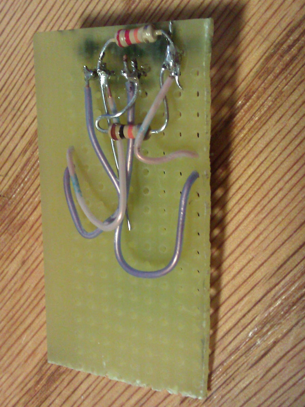 |
| Back |
 |
| Connected! |
Arduino and NS73M FM transmitter, RTTL Tones
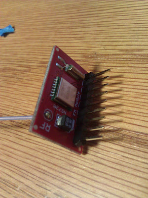
I got on of these Sparkfun NS73M FM transmitters for use with my Arduino. It is controlled over the SPI interface with three wires, and more importantly at 3.3v. Also, it has standard Left and Right inputs, so a MP3 player or, in my case, i used the Arduino Tone RTTL library to play some melodies. the hardest part of getting this thing to work is the SPI interface. Which is actually quite a bit easier since someone has aready done the hard work. All i had to do was hook it up according to the schematic i found(now attached) and change the frequency it transmits at.
To change the transmission frequency, you first want to go to the Vacant FM Frequency Finder and find a open channel in your area. Then, once you found one, a little bit of conversion is needed. I choose 96.7Mhz for my area.
So what you do is: (FMfreq + 0.304)/0.008192 where FMfreq is 96.7. That equals about 11792.
Then it needs to be converted to binary with Google: 11792 to binary which gets B10111000010000
Next, it must be 16 digits long, so add some zeros in front until you get 16 digits. I added two 0s: B0010111000010000.
Take the last 8 digits and that is register 3(00010000), and the first 8 digits are register 4(00101110).
In my code it looks like this:
spi_send(0x03, B00010000); //Register 3: Set broadcast freq to 96.7, lower byte
spi_send(0x04, B00101110); //Register 4: Set broadcast freq to 96.7, upper byte
Pics:
Code: The following sets the frequency and initializes the transmitter. this would be good for hooking a MP3 player to right and left inputs:
/*
12-1-2007
Cai Maver, caimaver(at)yahoo.com
ARRRduino+NS73M v0.3
This code allows an Arduino Diecimila to control an NS73M FM Transmitter Module (Arrr matey!)
This sets the NS73M (available from Sparkfun, SKU#: WRL-08482) to transmit
at 2mW with 75us pre-emphasis (the standard for North America) on 97.3 MHz.
Use this formula to determine the register values for a new transmitting frequency (f):
(f + 0.304)/0.008192 <-- use only the whole number and convert the result to
16-bit binary where the lower byte goes in register 3
and the upper byte goes in register 4
ex.: for 97.3 MHz, (97.3 + 0.304)/0.008192 = 11914.55...
11914 = B0010111010001010 so
Reg 3=B10001010
reg 4=B00101110
ex 96.7
//add "2" "0"s to the begginning... 16 long
11792 = B0010111000010000
reg 3 = B00010000 //second half goes here, 8 long
reg 4 = B00101110 //first half goes here
A future version of this code will allow for on-the-fly frequency changes
Thanks to Nathan Seidle at Sparkfun and Jim "ZAPNSPARK" G. for sharing their NS73M code!
*/
int CK = 12; //clock pin
int DA = 11; //data pin
int LA = 10; //latch pin
void setup(){
Serial.begin(9600); //begin Serial connection for debugging
pinMode(CK, OUTPUT);
pinMode(DA, OUTPUT);
pinMode(LA, OUTPUT);
digitalWrite(LA, LOW); //unlatch transmitter
delay(100); //Wait for VDD to settle
spi_send(0x0E, B00000101); //Software reset
spi_send(0x01, B10110100); //Register 1: forced subcarrier, pilot tone on
spi_send(0x02, B00000011); //Register 2: Unlock detect off, 2mW Tx Power
spi_send(0x03, B00010000); //Register 3: Set broadcast freq to 96.7, lower byte
spi_send(0x04, B00101110); //Register 4: Set broadcast freq to 96.7, upper byte
spi_send(0x08, B00011010); //Register 8: set Osc on band 2
spi_send(0x00, B10100001); //Register 0: 200mV audio input, 75us pre-emphasis on, crystal off, power on
spi_send(0x0E, B00000101); //Software reset
spi_send(0x06, B00011110); //Register 6: charge pumps at 320uA and 80 uA
Serial.print("Transmitting"); //for debugging
}
void loop()
{
}
void spi_send(byte reg, byte data) //routine to send Register Address and Data as LSB-first SPI
{
int x;
int n;
digitalWrite(LA, LOW);
for(x = 0 ; x < 4 ; x++) //send four-bit register address
{
digitalWrite(CK, LOW); //Toggle the SPI clock
n = (reg >> x) & 1; //n is the xth bit of the register byte
if (n == 1){
digitalWrite(DA, HIGH); //Put high bit on SPI data bus
}
else {
digitalWrite(DA, LOW); //Put low bit on SPI data bus
}
Serial.print(n); //send bit to serial connection for debugging
digitalWrite(CK, HIGH); //Toggle the SPI clock
}
for(x = 0 ; x < 8 ; x++) //send eight-bit register data
{
digitalWrite(CK, LOW); //Toggle the SPI clock
n = (data >> x) & 1;
if (n == 1){
digitalWrite(DA, HIGH); //Put high bit on SPI data bus
}
else {
digitalWrite(DA, LOW); //Put low bit on SPI data bus
}
Serial.print(n); //send bit to serial connection for debugging
digitalWrite(CK, HIGH); //Toggle the SPI clock
}
delayMicroseconds(1); //might not be needed, supposedly unstable command anyway
digitalWrite(LA, HIGH); //Latch this transfer
delayMicroseconds(4);
digitalWrite(LA, LOW);
digitalWrite(CK, LOW); //This is to keep CK pin at 0V at end of data transfer
Serial.print("\n"); // send new-line to serial for debugging
}
Code: The following sets the frequency, initializes the transmitter, AND it plays some popular melodies using the RTTL Tone library over FM 96.7:
/*
12-1-2007
Cai Maver, caimaver(at)yahoo.com
ARRRduino+NS73M v0.3
This code allows an Arduino Diecimila to control an NS73M FM Transmitter Module (Arrr matey!)
This sets the NS73M (available from Sparkfun, SKU#: WRL-08482) to transmit
at 2mW with 75us pre-emphasis (the standard for North America) on 97.3 MHz.
Use this formula to determine the register values for a new transmitting frequency (f):
(f + 0.304)/0.008192 <-- use only the whole number and convert the result to
16-bit binary where the lower byte goes in register 3
and the upper byte goes in register 4
ex.: for 97.3 MHz, (97.3 + 0.304)/0.008192 = 11914.55...
11914 = B0010111010001010 so
Reg 3=B10001010
reg 4=B00101110
ex 96.7, (96.7 + 0.304)/0.008192 = 11792.4
//convert to binary
11792 = B0010111000010000//add "2" "0"s to the begginning... 16 long
reg 3 = B00010000 //second half goes here, 8 long
reg 4 = B00101110 //first half goes here
Thanks to Nathan Seidle at Sparkfun and Jim "ZAPNSPARK" G. for sharing their NS73M code!
*/
int CK = 12; //clock pin
int DA = 11; //data pin
int LA = 10; //latch pin
#include <Tone.h>
Tone tone1;
#define OCTAVE_OFFSET 0
int notes[] = { 0,
NOTE_C4, NOTE_CS4, NOTE_D4, NOTE_DS4, NOTE_E4, NOTE_F4, NOTE_FS4, NOTE_G4, NOTE_GS4, NOTE_A4, NOTE_AS4, NOTE_B4,
NOTE_C5, NOTE_CS5, NOTE_D5, NOTE_DS5, NOTE_E5, NOTE_F5, NOTE_FS5, NOTE_G5, NOTE_GS5, NOTE_A5, NOTE_AS5, NOTE_B5,
NOTE_C6, NOTE_CS6, NOTE_D6, NOTE_DS6, NOTE_E6, NOTE_F6, NOTE_FS6, NOTE_G6, NOTE_GS6, NOTE_A6, NOTE_AS6, NOTE_B6,
NOTE_C7, NOTE_CS7, NOTE_D7, NOTE_DS7, NOTE_E7, NOTE_F7, NOTE_FS7, NOTE_G7, NOTE_GS7, NOTE_A7, NOTE_AS7, NOTE_B7
};
//char *song = "The Simpsons:d=4,o=5,b=160:c.6,e6,f#6,8a6,g.6,e6,c6,8a,8f#,8f#,8f#,2g,8p,8p,8f#,8f#,8f#,8g,a#.,8c6,8c6,8c6,c6";
//char *song = "Indiana:d=4,o=5,b=250:e,8p,8f,8g,8p,1c6,8p.,d,8p,8e,1f,p.,g,8p,8a,8b,8p,1f6,p,a,8p,8b,2c6,2d6,2e6,e,8p,8f,8g,8p,1c6,p,d6,8p,8e6,1f.6,g,8p,8g,e.6,8p,d6,8p,8g,e.6,8p,d6,8p,8g,f.6,8p,e6,8p,8d6,2c6";
//char *song = "TakeOnMe:d=4,o=4,b=160:8f#5,8f#5,8f#5,8d5,8p,8b,8p,8e5,8p,8e5,8p,8e5,8g#5,8g#5,8a5,8b5,8a5,8a5,8a5,8e5,8p,8d5,8p,8f#5,8p,8f#5,8p,8f#5,8e5,8e5,8f#5,8e5,8f#5,8f#5,8f#5,8d5,8p,8b,8p,8e5,8p,8e5,8p,8e5,8g#5,8g#5,8a5,8b5,8a5,8a5,8a5,8e5,8p,8d5,8p,8f#5,8p,8f#5,8p,8f#5,8e5,8e5";
//char *song = "Entertainer:d=4,o=5,b=140:8d,8d#,8e,c6,8e,c6,8e,2c.6,8c6,8d6,8d#6,8e6,8c6,8d6,e6,8b,d6,2c6,p,8d,8d#,8e,c6,8e,c6,8e,2c.6,8p,8a,8g,8f#,8a,8c6,e6,8d6,8c6,8a,2d6";
//char *song = "Muppets:d=4,o=5,b=250:c6,c6,a,b,8a,b,g,p,c6,c6,a,8b,8a,8p,g.,p,e,e,g,f,8e,f,8c6,8c,8d,e,8e,8e,8p,8e,g,2p,c6,c6,a,b,8a,b,g,p,c6,c6,a,8b,a,g.,p,e,e,g,f,8e,f,8c6,8c,8d,e,8e,d,8d,c";
//char *song = "Xfiles:d=4,o=5,b=125:e,b,a,b,d6,2b.,1p,e,b,a,b,e6,2b.,1p,g6,f#6,e6,d6,e6,2b.,1p,g6,f#6,e6,d6,f#6,2b.,1p,e,b,a,b,d6,2b.,1p,e,b,a,b,e6,2b.,1p,e6,2b.";
//char *song = "Looney:d=4,o=5,b=140:32p,c6,8f6,8e6,8d6,8c6,a.,8c6,8f6,8e6,8d6,8d#6,e.6,8e6,8e6,8c6,8d6,8c6,8e6,8c6,8d6,8a,8c6,8g,8a#,8a,8f";
//char *song = "20thCenFox:d=16,o=5,b=140:b,8p,b,b,2b,p,c6,32p,b,32p,c6,32p,b,32p,c6,32p,b,8p,b,b,b,32p,b,32p,b,32p,b,32p,b,32p,b,32p,b,32p,g#,32p,a,32p,b,8p,b,b,2b,4p,8e,8g#,8b,1c#6,8f#,8a,8c#6,1e6,8a,8c#6,8e6,1e6,8b,8g#,8a,2b";
//char *song = "Bond:d=4,o=5,b=80:32p,16c#6,32d#6,32d#6,16d#6,8d#6,16c#6,16c#6,16c#6,16c#6,32e6,32e6,16e6,8e6,16d#6,16d#6,16d#6,16c#6,32d#6,32d#6,16d#6,8d#6,16c#6,16c#6,16c#6,16c#6,32e6,32e6,16e6,8e6,16d#6,16d6,16c#6,16c#7,c.7,16g#6,16f#6,g#.6";
//char *song = "MASH:d=8,o=5,b=140:4a,4g,f#,g,p,f#,p,g,p,f#,p,2e.,p,f#,e,4f#,e,f#,p,e,p,4d.,p,f#,4e,d,e,p,d,p,e,p,d,p,2c#.,p,d,c#,4d,c#,d,p,e,p,4f#,p,a,p,4b,a,b,p,a,p,b,p,2a.,4p,a,b,a,4b,a,b,p,2a.,a,4f#,a,b,p,d6,p,4e.6,d6,b,p,a,p,2b";
//char *song = "StarWars:d=4,o=5,b=45:32p,32f#,32f#,32f#,8b.,8f#.6,32e6,32d#6,32c#6,8b.6,16f#.6,32e6,32d#6,32c#6,8b.6,16f#.6,32e6,32d#6,32e6,8c#.6,32f#,32f#,32f#,8b.,8f#.6,32e6,32d#6,32c#6,8b.6,16f#.6,32e6,32d#6,32c#6,8b.6,16f#.6,32e6,32d#6,32e6,8c#6";
//char *song = "GoodBad:d=4,o=5,b=56:32p,32a#,32d#6,32a#,32d#6,8a#.,16f#.,16g#.,d#,32a#,32d#6,32a#,32d#6,8a#.,16f#.,16g#.,c#6,32a#,32d#6,32a#,32d#6,8a#.,16f#.,32f.,32d#.,c#,32a#,32d#6,32a#,32d#6,8a#.,16g#.,d#";
//char *song = "TopGun:d=4,o=4,b=31:32p,16c#,16g#,16g#,32f#,32f,32f#,32f,16d#,16d#,32c#,32d#,16f,32d#,32f,16f#,32f,32c#,16f,d#,16c#,16g#,16g#,32f#,32f,32f#,32f,16d#,16d#,32c#,32d#,16f,32d#,32f,16f#,32f,32c#,g#";
//char *song = "A-Team:d=8,o=5,b=125:4d#6,a#,2d#6,16p,g#,4a#,4d#.,p,16g,16a#,d#6,a#,f6,2d#6,16p,c#.6,16c6,16a#,g#.,2a#";
//char *song = "Flinstones:d=4,o=5,b=40:32p,16f6,16a#,16a#6,32g6,16f6,16a#.,16f6,32d#6,32d6,32d6,32d#6,32f6,16a#,16c6,d6,16f6,16a#.,16a#6,32g6,16f6,16a#.,32f6,32f6,32d#6,32d6,32d6,32d#6,32f6,16a#,16c6,a#,16a6,16d.6,16a#6,32a6,32a6,32g6,32f#6,32a6,8g6,16g6,16c.6,32a6,32a6,32g6,32g6,32f6,32e6,32g6,8f6,16f6,16a#.,16a#6,32g6,16f6,16a#.,16f6,32d#6,32d6,32d6,32d#6,32f6,16a#,16c.6,32d6,32d#6,32f6,16a#,16c.6,32d6,32d#6,32f6,16a#6,16c7,8a#.6";
char *song = "Jeopardy:d=4,o=6,b=125:c,f,c,f5,c,f,2c,c,f,c,f,a.,8g,8f,8e,8d,8c#,c,f,c,f5,c,f,2c,f.,8d,c,a#5,a5,g5,f5,p,d#,g#,d#,g#5,d#,g#,2d#,d#,g#,d#,g#,c.7,8a#,8g#,8g,8f,8e,d#,g#,d#,g#5,d#,g#,2d#,g#.,8f,d#,c#,c,p,a#5,p,g#.5,d#,g#";
//char *song = "Gadget:d=16,o=5,b=50:32d#,32f,32f#,32g#,a#,f#,a,f,g#,f#,32d#,32f,32f#,32g#,a#,d#6,4d6,32d#,32f,32f#,32g#,a#,f#,a,f,g#,f#,8d#";
//char *song = "Smurfs:d=32,o=5,b=200:4c#6,16p,4f#6,p,16c#6,p,8d#6,p,8b,p,4g#,16p,4c#6,p,16a#,p,8f#,p,8a#,p,4g#,4p,g#,p,a#,p,b,p,c6,p,4c#6,16p,4f#6,p,16c#6,p,8d#6,p,8b,p,4g#,16p,4c#6,p,16a#,p,8b,p,8f,p,4f#";
//char *song = "MahnaMahna:d=16,o=6,b=125:c#,c.,b5,8a#.5,8f.,4g#,a#,g.,4d#,8p,c#,c.,b5,8a#.5,8f.,g#.,8a#.,4g,8p,c#,c.,b5,8a#.5,8f.,4g#,f,g.,8d#.,f,g.,8d#.,f,8g,8d#.,f,8g,d#,8c,a#5,8d#.,8d#.,4d#,8d#.";
//char *song = "LeisureSuit:d=16,o=6,b=56:f.5,f#.5,g.5,g#5,32a#5,f5,g#.5,a#.5,32f5,g#5,32a#5,g#5,8c#.,a#5,32c#,a5,a#.5,c#.,32a5,a#5,32c#,d#,8e,c#.,f.,f.,f.,f.,f,32e,d#,8d,a#.5,e,32f,e,32f,c#,d#.,c#";
//char *song = "MissionImp:d=16,o=6,b=95:32d,32d#,32d,32d#,32d,32d#,32d,32d#,32d,32d,32d#,32e,32f,32f#,32g,g,8p,g,8p,a#,p,c7,p,g,8p,g,8p,f,p,f#,p,g,8p,g,8p,a#,p,c7,p,g,8p,g,8p,f,p,f#,p,a#,g,2d,32p,a#,g,2c#,32p,a#,g,2c,a#5,8c,2p,32p,a#5,g5,2f#,32p,a#5,g5,2f,32p,a#5,g5,2e,d#,8d";
void setup(){
Serial.begin(9600); //begin Serial connection for debugging
tone1.begin(8);
pinMode(CK, OUTPUT);
pinMode(DA, OUTPUT);
pinMode(LA, OUTPUT);
digitalWrite(LA, LOW); //unlatch transmitter
delay(100); //Wait for VDD to settle
spi_send(0x0E, B00000101); //Software reset
spi_send(0x01, B10110100); //Register 1: forced subcarrier, pilot tone on
spi_send(0x02, B00000011); //Register 2: Unlock detect off, 2mW Tx Power
spi_send(0x03, B00010000); //Register 3: Set broadcast freq to 96.7, lower byte
spi_send(0x04, B00101110); //Register 4: Set broadcast freq to 96.7, upper byte
spi_send(0x08, B00011010); //Register 8: set Osc on band 2
spi_send(0x00, B10100001); //Register 0: 200mV audio input, 75us pre-emphasis on, crystal off, power on
spi_send(0x0E, B00000101); //Software reset
spi_send(0x06, B00011110); //Register 6: charge pumps at 320uA and 80 uA
Serial.print("Transmitting"); //for debugging
}
#define isdigit(n) (n >= '0' && n <= '9')
void play_rtttl(char *p)
{
// Absolutely no error checking in here
byte default_dur = 4;
byte default_oct = 6;
int bpm = 63;
int num;
long wholenote;
long duration;
byte note;
byte scale;
// format: d=N,o=N,b=NNN:
// find the start (skip name, etc)
while(*p != ':') p++; // ignore name
p++; // skip ':'
// get default duration
if(*p == 'd')
{
p++; p++; // skip "d="
num = 0;
while(isdigit(*p))
{
num = (num * 10) + (*p++ - '0');
}
if(num > 0) default_dur = num;
p++; // skip comma
}
Serial.print("ddur: "); Serial.println(default_dur, 10);
// get default octave
if(*p == 'o')
{
p++; p++; // skip "o="
num = *p++ - '0';
if(num >= 3 && num <=7) default_oct = num;
p++; // skip comma
}
Serial.print("doct: "); Serial.println(default_oct, 10);
// get BPM
if(*p == 'b')
{
p++; p++; // skip "b="
num = 0;
while(isdigit(*p))
{
num = (num * 10) + (*p++ - '0');
}
bpm = num;
p++; // skip colon
}
Serial.print("bpm: "); Serial.println(bpm, 10);
// BPM usually expresses the number of quarter notes per minute
wholenote = (60 * 1000L / bpm) * 4; // this is the time for whole note (in milliseconds)
Serial.print("wn: "); Serial.println(wholenote, 10);
// now begin note loop
while(*p)
{
// first, get note duration, if available
num = 0;
while(isdigit(*p))
{
num = (num * 10) + (*p++ - '0');
}
if(num) duration = wholenote / num;
else duration = wholenote / default_dur; // we will need to check if we are a dotted note after
// now get the note
note = 0;
switch(*p)
{
case 'c':
note = 1;
break;
case 'd':
note = 3;
break;
case 'e':
note = 5;
break;
case 'f':
note = 6;
break;
case 'g':
note = 8;
break;
case 'a':
note = 10;
break;
case 'b':
note = 12;
break;
case 'p':
default:
note = 0;
}
p++;
// now, get optional '#' sharp
if(*p == '#')
{
note++;
p++;
}
// now, get optional '.' dotted note
if(*p == '.')
{
duration += duration/2;
p++;
}
// now, get scale
if(isdigit(*p))
{
scale = *p - '0';
p++;
}
else
{
scale = default_oct;
}
scale += OCTAVE_OFFSET;
if(*p == ',')
p++; // skip comma for next note (or we may be at the end)
// now play the note
if(note)
{
Serial.print("Playing: ");
Serial.print(scale, 10); Serial.print(' ');
Serial.print(note, 10); Serial.print(" (");
Serial.print(notes[(scale - 4) * 12 + note], 10);
Serial.print(") ");
Serial.println(duration, 10);
tone1.play(notes[(scale - 4) * 12 + note]);
delay(duration);
tone1.stop();
}
else
{
Serial.print("Pausing: ");
Serial.println(duration, 10);
delay(duration);
}
}
}
void loop(void)
{
play_rtttl(song);
Serial.println("Done.");
delay(1000);
}
void spi_send(byte reg, byte data) //routine to send Register Address and Data as LSB-first SPI
{
int x;
int n;
digitalWrite(LA, LOW);
for(x = 0 ; x < 4 ; x++) //send four-bit register address
{
digitalWrite(CK, LOW); //Toggle the SPI clock
n = (reg >> x) & 1; //n is the xth bit of the register byte
if (n == 1){
digitalWrite(DA, HIGH); //Put high bit on SPI data bus
}
else {
digitalWrite(DA, LOW); //Put low bit on SPI data bus
}
Serial.print(n); //send bit to serial connection for debugging
digitalWrite(CK, HIGH); //Toggle the SPI clock
}
for(x = 0 ; x < 8 ; x++) //send eight-bit register data
{
digitalWrite(CK, LOW); //Toggle the SPI clock
n = (data >> x) & 1;
if (n == 1){
digitalWrite(DA, HIGH); //Put high bit on SPI data bus
}
else {
digitalWrite(DA, LOW); //Put low bit on SPI data bus
}
Serial.print(n); //send bit to serial connection for debugging
digitalWrite(CK, HIGH); //Toggle the SPI clock
}
delayMicroseconds(1); //might not be needed, supposedly unstable command anyway
digitalWrite(LA, HIGH); //Latch this transfer
delayMicroseconds(4);
digitalWrite(LA, LOW);
digitalWrite(CK, LOW); //This is to keep CK pin at 0V at end of data transfer
Serial.print("\n"); // send new-line to serial for debugging
}
To change the transmission frequency, you first want to go to the Vacant FM Frequency Finder and find a open channel in your area. Then, once you found one, a little bit of conversion is needed. I choose 96.7Mhz for my area.
So what you do is: (FMfreq + 0.304)/0.008192 where FMfreq is 96.7. That equals about 11792.
Then it needs to be converted to binary with Google: 11792 to binary which gets B10111000010000
Next, it must be 16 digits long, so add some zeros in front until you get 16 digits. I added two 0s: B0010111000010000.
Take the last 8 digits and that is register 3(00010000), and the first 8 digits are register 4(00101110).
In my code it looks like this:
spi_send(0x03, B00010000); //Register 3: Set broadcast freq to 96.7, lower byte
spi_send(0x04, B00101110); //Register 4: Set broadcast freq to 96.7, upper byte
Pics:
 |
| Note how i soldered the pins: easier to use on breadboard with labels facing up. |

 |
| Scheme for Arduino |
Code: The following sets the frequency and initializes the transmitter. this would be good for hooking a MP3 player to right and left inputs:
/*
12-1-2007
Cai Maver, caimaver(at)yahoo.com
ARRRduino+NS73M v0.3
This code allows an Arduino Diecimila to control an NS73M FM Transmitter Module (Arrr matey!)
This sets the NS73M (available from Sparkfun, SKU#: WRL-08482) to transmit
at 2mW with 75us pre-emphasis (the standard for North America) on 97.3 MHz.
Use this formula to determine the register values for a new transmitting frequency (f):
(f + 0.304)/0.008192 <-- use only the whole number and convert the result to
16-bit binary where the lower byte goes in register 3
and the upper byte goes in register 4
ex.: for 97.3 MHz, (97.3 + 0.304)/0.008192 = 11914.55...
11914 = B0010111010001010 so
Reg 3=B10001010
reg 4=B00101110
ex 96.7
//add "2" "0"s to the begginning... 16 long
11792 = B0010111000010000
reg 3 = B00010000 //second half goes here, 8 long
reg 4 = B00101110 //first half goes here
A future version of this code will allow for on-the-fly frequency changes
Thanks to Nathan Seidle at Sparkfun and Jim "ZAPNSPARK" G. for sharing their NS73M code!
*/
int CK = 12; //clock pin
int DA = 11; //data pin
int LA = 10; //latch pin
void setup(){
Serial.begin(9600); //begin Serial connection for debugging
pinMode(CK, OUTPUT);
pinMode(DA, OUTPUT);
pinMode(LA, OUTPUT);
digitalWrite(LA, LOW); //unlatch transmitter
delay(100); //Wait for VDD to settle
spi_send(0x0E, B00000101); //Software reset
spi_send(0x01, B10110100); //Register 1: forced subcarrier, pilot tone on
spi_send(0x02, B00000011); //Register 2: Unlock detect off, 2mW Tx Power
spi_send(0x03, B00010000); //Register 3: Set broadcast freq to 96.7, lower byte
spi_send(0x04, B00101110); //Register 4: Set broadcast freq to 96.7, upper byte
spi_send(0x08, B00011010); //Register 8: set Osc on band 2
spi_send(0x00, B10100001); //Register 0: 200mV audio input, 75us pre-emphasis on, crystal off, power on
spi_send(0x0E, B00000101); //Software reset
spi_send(0x06, B00011110); //Register 6: charge pumps at 320uA and 80 uA
Serial.print("Transmitting"); //for debugging
}
void loop()
{
}
void spi_send(byte reg, byte data) //routine to send Register Address and Data as LSB-first SPI
{
int x;
int n;
digitalWrite(LA, LOW);
for(x = 0 ; x < 4 ; x++) //send four-bit register address
{
digitalWrite(CK, LOW); //Toggle the SPI clock
n = (reg >> x) & 1; //n is the xth bit of the register byte
if (n == 1){
digitalWrite(DA, HIGH); //Put high bit on SPI data bus
}
else {
digitalWrite(DA, LOW); //Put low bit on SPI data bus
}
Serial.print(n); //send bit to serial connection for debugging
digitalWrite(CK, HIGH); //Toggle the SPI clock
}
for(x = 0 ; x < 8 ; x++) //send eight-bit register data
{
digitalWrite(CK, LOW); //Toggle the SPI clock
n = (data >> x) & 1;
if (n == 1){
digitalWrite(DA, HIGH); //Put high bit on SPI data bus
}
else {
digitalWrite(DA, LOW); //Put low bit on SPI data bus
}
Serial.print(n); //send bit to serial connection for debugging
digitalWrite(CK, HIGH); //Toggle the SPI clock
}
delayMicroseconds(1); //might not be needed, supposedly unstable command anyway
digitalWrite(LA, HIGH); //Latch this transfer
delayMicroseconds(4);
digitalWrite(LA, LOW);
digitalWrite(CK, LOW); //This is to keep CK pin at 0V at end of data transfer
Serial.print("\n"); // send new-line to serial for debugging
}
Code: The following sets the frequency, initializes the transmitter, AND it plays some popular melodies using the RTTL Tone library over FM 96.7:
/*
12-1-2007
Cai Maver, caimaver(at)yahoo.com
ARRRduino+NS73M v0.3
This code allows an Arduino Diecimila to control an NS73M FM Transmitter Module (Arrr matey!)
This sets the NS73M (available from Sparkfun, SKU#: WRL-08482) to transmit
at 2mW with 75us pre-emphasis (the standard for North America) on 97.3 MHz.
Use this formula to determine the register values for a new transmitting frequency (f):
(f + 0.304)/0.008192 <-- use only the whole number and convert the result to
16-bit binary where the lower byte goes in register 3
and the upper byte goes in register 4
ex.: for 97.3 MHz, (97.3 + 0.304)/0.008192 = 11914.55...
11914 = B0010111010001010 so
Reg 3=B10001010
reg 4=B00101110
ex 96.7, (96.7 + 0.304)/0.008192 = 11792.4
//convert to binary
11792 = B0010111000010000//add "2" "0"s to the begginning... 16 long
reg 3 = B00010000 //second half goes here, 8 long
reg 4 = B00101110 //first half goes here
Thanks to Nathan Seidle at Sparkfun and Jim "ZAPNSPARK" G. for sharing their NS73M code!
*/
int CK = 12; //clock pin
int DA = 11; //data pin
int LA = 10; //latch pin
#include <Tone.h>
Tone tone1;
#define OCTAVE_OFFSET 0
int notes[] = { 0,
NOTE_C4, NOTE_CS4, NOTE_D4, NOTE_DS4, NOTE_E4, NOTE_F4, NOTE_FS4, NOTE_G4, NOTE_GS4, NOTE_A4, NOTE_AS4, NOTE_B4,
NOTE_C5, NOTE_CS5, NOTE_D5, NOTE_DS5, NOTE_E5, NOTE_F5, NOTE_FS5, NOTE_G5, NOTE_GS5, NOTE_A5, NOTE_AS5, NOTE_B5,
NOTE_C6, NOTE_CS6, NOTE_D6, NOTE_DS6, NOTE_E6, NOTE_F6, NOTE_FS6, NOTE_G6, NOTE_GS6, NOTE_A6, NOTE_AS6, NOTE_B6,
NOTE_C7, NOTE_CS7, NOTE_D7, NOTE_DS7, NOTE_E7, NOTE_F7, NOTE_FS7, NOTE_G7, NOTE_GS7, NOTE_A7, NOTE_AS7, NOTE_B7
};
//char *song = "The Simpsons:d=4,o=5,b=160:c.6,e6,f#6,8a6,g.6,e6,c6,8a,8f#,8f#,8f#,2g,8p,8p,8f#,8f#,8f#,8g,a#.,8c6,8c6,8c6,c6";
//char *song = "Indiana:d=4,o=5,b=250:e,8p,8f,8g,8p,1c6,8p.,d,8p,8e,1f,p.,g,8p,8a,8b,8p,1f6,p,a,8p,8b,2c6,2d6,2e6,e,8p,8f,8g,8p,1c6,p,d6,8p,8e6,1f.6,g,8p,8g,e.6,8p,d6,8p,8g,e.6,8p,d6,8p,8g,f.6,8p,e6,8p,8d6,2c6";
//char *song = "TakeOnMe:d=4,o=4,b=160:8f#5,8f#5,8f#5,8d5,8p,8b,8p,8e5,8p,8e5,8p,8e5,8g#5,8g#5,8a5,8b5,8a5,8a5,8a5,8e5,8p,8d5,8p,8f#5,8p,8f#5,8p,8f#5,8e5,8e5,8f#5,8e5,8f#5,8f#5,8f#5,8d5,8p,8b,8p,8e5,8p,8e5,8p,8e5,8g#5,8g#5,8a5,8b5,8a5,8a5,8a5,8e5,8p,8d5,8p,8f#5,8p,8f#5,8p,8f#5,8e5,8e5";
//char *song = "Entertainer:d=4,o=5,b=140:8d,8d#,8e,c6,8e,c6,8e,2c.6,8c6,8d6,8d#6,8e6,8c6,8d6,e6,8b,d6,2c6,p,8d,8d#,8e,c6,8e,c6,8e,2c.6,8p,8a,8g,8f#,8a,8c6,e6,8d6,8c6,8a,2d6";
//char *song = "Muppets:d=4,o=5,b=250:c6,c6,a,b,8a,b,g,p,c6,c6,a,8b,8a,8p,g.,p,e,e,g,f,8e,f,8c6,8c,8d,e,8e,8e,8p,8e,g,2p,c6,c6,a,b,8a,b,g,p,c6,c6,a,8b,a,g.,p,e,e,g,f,8e,f,8c6,8c,8d,e,8e,d,8d,c";
//char *song = "Xfiles:d=4,o=5,b=125:e,b,a,b,d6,2b.,1p,e,b,a,b,e6,2b.,1p,g6,f#6,e6,d6,e6,2b.,1p,g6,f#6,e6,d6,f#6,2b.,1p,e,b,a,b,d6,2b.,1p,e,b,a,b,e6,2b.,1p,e6,2b.";
//char *song = "Looney:d=4,o=5,b=140:32p,c6,8f6,8e6,8d6,8c6,a.,8c6,8f6,8e6,8d6,8d#6,e.6,8e6,8e6,8c6,8d6,8c6,8e6,8c6,8d6,8a,8c6,8g,8a#,8a,8f";
//char *song = "20thCenFox:d=16,o=5,b=140:b,8p,b,b,2b,p,c6,32p,b,32p,c6,32p,b,32p,c6,32p,b,8p,b,b,b,32p,b,32p,b,32p,b,32p,b,32p,b,32p,b,32p,g#,32p,a,32p,b,8p,b,b,2b,4p,8e,8g#,8b,1c#6,8f#,8a,8c#6,1e6,8a,8c#6,8e6,1e6,8b,8g#,8a,2b";
//char *song = "Bond:d=4,o=5,b=80:32p,16c#6,32d#6,32d#6,16d#6,8d#6,16c#6,16c#6,16c#6,16c#6,32e6,32e6,16e6,8e6,16d#6,16d#6,16d#6,16c#6,32d#6,32d#6,16d#6,8d#6,16c#6,16c#6,16c#6,16c#6,32e6,32e6,16e6,8e6,16d#6,16d6,16c#6,16c#7,c.7,16g#6,16f#6,g#.6";
//char *song = "MASH:d=8,o=5,b=140:4a,4g,f#,g,p,f#,p,g,p,f#,p,2e.,p,f#,e,4f#,e,f#,p,e,p,4d.,p,f#,4e,d,e,p,d,p,e,p,d,p,2c#.,p,d,c#,4d,c#,d,p,e,p,4f#,p,a,p,4b,a,b,p,a,p,b,p,2a.,4p,a,b,a,4b,a,b,p,2a.,a,4f#,a,b,p,d6,p,4e.6,d6,b,p,a,p,2b";
//char *song = "StarWars:d=4,o=5,b=45:32p,32f#,32f#,32f#,8b.,8f#.6,32e6,32d#6,32c#6,8b.6,16f#.6,32e6,32d#6,32c#6,8b.6,16f#.6,32e6,32d#6,32e6,8c#.6,32f#,32f#,32f#,8b.,8f#.6,32e6,32d#6,32c#6,8b.6,16f#.6,32e6,32d#6,32c#6,8b.6,16f#.6,32e6,32d#6,32e6,8c#6";
//char *song = "GoodBad:d=4,o=5,b=56:32p,32a#,32d#6,32a#,32d#6,8a#.,16f#.,16g#.,d#,32a#,32d#6,32a#,32d#6,8a#.,16f#.,16g#.,c#6,32a#,32d#6,32a#,32d#6,8a#.,16f#.,32f.,32d#.,c#,32a#,32d#6,32a#,32d#6,8a#.,16g#.,d#";
//char *song = "TopGun:d=4,o=4,b=31:32p,16c#,16g#,16g#,32f#,32f,32f#,32f,16d#,16d#,32c#,32d#,16f,32d#,32f,16f#,32f,32c#,16f,d#,16c#,16g#,16g#,32f#,32f,32f#,32f,16d#,16d#,32c#,32d#,16f,32d#,32f,16f#,32f,32c#,g#";
//char *song = "A-Team:d=8,o=5,b=125:4d#6,a#,2d#6,16p,g#,4a#,4d#.,p,16g,16a#,d#6,a#,f6,2d#6,16p,c#.6,16c6,16a#,g#.,2a#";
//char *song = "Flinstones:d=4,o=5,b=40:32p,16f6,16a#,16a#6,32g6,16f6,16a#.,16f6,32d#6,32d6,32d6,32d#6,32f6,16a#,16c6,d6,16f6,16a#.,16a#6,32g6,16f6,16a#.,32f6,32f6,32d#6,32d6,32d6,32d#6,32f6,16a#,16c6,a#,16a6,16d.6,16a#6,32a6,32a6,32g6,32f#6,32a6,8g6,16g6,16c.6,32a6,32a6,32g6,32g6,32f6,32e6,32g6,8f6,16f6,16a#.,16a#6,32g6,16f6,16a#.,16f6,32d#6,32d6,32d6,32d#6,32f6,16a#,16c.6,32d6,32d#6,32f6,16a#,16c.6,32d6,32d#6,32f6,16a#6,16c7,8a#.6";
char *song = "Jeopardy:d=4,o=6,b=125:c,f,c,f5,c,f,2c,c,f,c,f,a.,8g,8f,8e,8d,8c#,c,f,c,f5,c,f,2c,f.,8d,c,a#5,a5,g5,f5,p,d#,g#,d#,g#5,d#,g#,2d#,d#,g#,d#,g#,c.7,8a#,8g#,8g,8f,8e,d#,g#,d#,g#5,d#,g#,2d#,g#.,8f,d#,c#,c,p,a#5,p,g#.5,d#,g#";
//char *song = "Gadget:d=16,o=5,b=50:32d#,32f,32f#,32g#,a#,f#,a,f,g#,f#,32d#,32f,32f#,32g#,a#,d#6,4d6,32d#,32f,32f#,32g#,a#,f#,a,f,g#,f#,8d#";
//char *song = "Smurfs:d=32,o=5,b=200:4c#6,16p,4f#6,p,16c#6,p,8d#6,p,8b,p,4g#,16p,4c#6,p,16a#,p,8f#,p,8a#,p,4g#,4p,g#,p,a#,p,b,p,c6,p,4c#6,16p,4f#6,p,16c#6,p,8d#6,p,8b,p,4g#,16p,4c#6,p,16a#,p,8b,p,8f,p,4f#";
//char *song = "MahnaMahna:d=16,o=6,b=125:c#,c.,b5,8a#.5,8f.,4g#,a#,g.,4d#,8p,c#,c.,b5,8a#.5,8f.,g#.,8a#.,4g,8p,c#,c.,b5,8a#.5,8f.,4g#,f,g.,8d#.,f,g.,8d#.,f,8g,8d#.,f,8g,d#,8c,a#5,8d#.,8d#.,4d#,8d#.";
//char *song = "LeisureSuit:d=16,o=6,b=56:f.5,f#.5,g.5,g#5,32a#5,f5,g#.5,a#.5,32f5,g#5,32a#5,g#5,8c#.,a#5,32c#,a5,a#.5,c#.,32a5,a#5,32c#,d#,8e,c#.,f.,f.,f.,f.,f,32e,d#,8d,a#.5,e,32f,e,32f,c#,d#.,c#";
//char *song = "MissionImp:d=16,o=6,b=95:32d,32d#,32d,32d#,32d,32d#,32d,32d#,32d,32d,32d#,32e,32f,32f#,32g,g,8p,g,8p,a#,p,c7,p,g,8p,g,8p,f,p,f#,p,g,8p,g,8p,a#,p,c7,p,g,8p,g,8p,f,p,f#,p,a#,g,2d,32p,a#,g,2c#,32p,a#,g,2c,a#5,8c,2p,32p,a#5,g5,2f#,32p,a#5,g5,2f,32p,a#5,g5,2e,d#,8d";
void setup(){
Serial.begin(9600); //begin Serial connection for debugging
tone1.begin(8);
pinMode(CK, OUTPUT);
pinMode(DA, OUTPUT);
pinMode(LA, OUTPUT);
digitalWrite(LA, LOW); //unlatch transmitter
delay(100); //Wait for VDD to settle
spi_send(0x0E, B00000101); //Software reset
spi_send(0x01, B10110100); //Register 1: forced subcarrier, pilot tone on
spi_send(0x02, B00000011); //Register 2: Unlock detect off, 2mW Tx Power
spi_send(0x03, B00010000); //Register 3: Set broadcast freq to 96.7, lower byte
spi_send(0x04, B00101110); //Register 4: Set broadcast freq to 96.7, upper byte
spi_send(0x08, B00011010); //Register 8: set Osc on band 2
spi_send(0x00, B10100001); //Register 0: 200mV audio input, 75us pre-emphasis on, crystal off, power on
spi_send(0x0E, B00000101); //Software reset
spi_send(0x06, B00011110); //Register 6: charge pumps at 320uA and 80 uA
Serial.print("Transmitting"); //for debugging
}
#define isdigit(n) (n >= '0' && n <= '9')
void play_rtttl(char *p)
{
// Absolutely no error checking in here
byte default_dur = 4;
byte default_oct = 6;
int bpm = 63;
int num;
long wholenote;
long duration;
byte note;
byte scale;
// format: d=N,o=N,b=NNN:
// find the start (skip name, etc)
while(*p != ':') p++; // ignore name
p++; // skip ':'
// get default duration
if(*p == 'd')
{
p++; p++; // skip "d="
num = 0;
while(isdigit(*p))
{
num = (num * 10) + (*p++ - '0');
}
if(num > 0) default_dur = num;
p++; // skip comma
}
Serial.print("ddur: "); Serial.println(default_dur, 10);
// get default octave
if(*p == 'o')
{
p++; p++; // skip "o="
num = *p++ - '0';
if(num >= 3 && num <=7) default_oct = num;
p++; // skip comma
}
Serial.print("doct: "); Serial.println(default_oct, 10);
// get BPM
if(*p == 'b')
{
p++; p++; // skip "b="
num = 0;
while(isdigit(*p))
{
num = (num * 10) + (*p++ - '0');
}
bpm = num;
p++; // skip colon
}
Serial.print("bpm: "); Serial.println(bpm, 10);
// BPM usually expresses the number of quarter notes per minute
wholenote = (60 * 1000L / bpm) * 4; // this is the time for whole note (in milliseconds)
Serial.print("wn: "); Serial.println(wholenote, 10);
// now begin note loop
while(*p)
{
// first, get note duration, if available
num = 0;
while(isdigit(*p))
{
num = (num * 10) + (*p++ - '0');
}
if(num) duration = wholenote / num;
else duration = wholenote / default_dur; // we will need to check if we are a dotted note after
// now get the note
note = 0;
switch(*p)
{
case 'c':
note = 1;
break;
case 'd':
note = 3;
break;
case 'e':
note = 5;
break;
case 'f':
note = 6;
break;
case 'g':
note = 8;
break;
case 'a':
note = 10;
break;
case 'b':
note = 12;
break;
case 'p':
default:
note = 0;
}
p++;
// now, get optional '#' sharp
if(*p == '#')
{
note++;
p++;
}
// now, get optional '.' dotted note
if(*p == '.')
{
duration += duration/2;
p++;
}
// now, get scale
if(isdigit(*p))
{
scale = *p - '0';
p++;
}
else
{
scale = default_oct;
}
scale += OCTAVE_OFFSET;
if(*p == ',')
p++; // skip comma for next note (or we may be at the end)
// now play the note
if(note)
{
Serial.print("Playing: ");
Serial.print(scale, 10); Serial.print(' ');
Serial.print(note, 10); Serial.print(" (");
Serial.print(notes[(scale - 4) * 12 + note], 10);
Serial.print(") ");
Serial.println(duration, 10);
tone1.play(notes[(scale - 4) * 12 + note]);
delay(duration);
tone1.stop();
}
else
{
Serial.print("Pausing: ");
Serial.println(duration, 10);
delay(duration);
}
}
}
void loop(void)
{
play_rtttl(song);
Serial.println("Done.");
delay(1000);
}
void spi_send(byte reg, byte data) //routine to send Register Address and Data as LSB-first SPI
{
int x;
int n;
digitalWrite(LA, LOW);
for(x = 0 ; x < 4 ; x++) //send four-bit register address
{
digitalWrite(CK, LOW); //Toggle the SPI clock
n = (reg >> x) & 1; //n is the xth bit of the register byte
if (n == 1){
digitalWrite(DA, HIGH); //Put high bit on SPI data bus
}
else {
digitalWrite(DA, LOW); //Put low bit on SPI data bus
}
Serial.print(n); //send bit to serial connection for debugging
digitalWrite(CK, HIGH); //Toggle the SPI clock
}
for(x = 0 ; x < 8 ; x++) //send eight-bit register data
{
digitalWrite(CK, LOW); //Toggle the SPI clock
n = (data >> x) & 1;
if (n == 1){
digitalWrite(DA, HIGH); //Put high bit on SPI data bus
}
else {
digitalWrite(DA, LOW); //Put low bit on SPI data bus
}
Serial.print(n); //send bit to serial connection for debugging
digitalWrite(CK, HIGH); //Toggle the SPI clock
}
delayMicroseconds(1); //might not be needed, supposedly unstable command anyway
digitalWrite(LA, HIGH); //Latch this transfer
delayMicroseconds(4);
digitalWrite(LA, LOW);
digitalWrite(CK, LOW); //This is to keep CK pin at 0V at end of data transfer
Serial.print("\n"); // send new-line to serial for debugging
}
Subscribe to:
Posts (Atom)