Note: this post is not yet complete.
Basics
What is a plane? Wikipedia says: "A fixed wing aircraft is an aircraft capable of flight using wings that generate lift due to the vehicle's forward airspeed and the shape of the wings. A powered fixed-wing aircraft that is propelled forward by thrust from a jet engine or propeller is typically called an aeroplane, airplane, or simply a plane." Here is a basic picture:
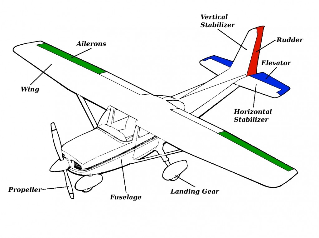
Fuselage - This is the base of the entire aircraft as it holds everything from the motor to the control surfaces. typically made out of foam or wood
Propeller - This is turned by the motor and because of its shape, it generates thrust as it spins. It could be described as "scooping" the air and pushing it back. to provide horizontal thrust for the plane, pulling it forward.
Motor - This can either be electric(brushed or brushless) or a gas/nitro/whatever motor. This sits right behind the propeller and most likely directly(no gears) drives the propeller. I use a brushless motor (more efficient, less wear), but gas is still pretty popular.
ESC - This pertains to electric motors only (brushed/brushless). This is connected to the battery and motor so that a signal (later) can change the speed of the motor and therefor the amount of speed/thrust of the plane.
Batery - This provides electricity for the servos, RX, motor and other stuff. Most commonly a LiPo because of its high power to weight ratio.
RX(aka the receiver) - This receives signals from the TX(transmitter) and changes the motor speed, servo positions, and other stuff so that the plane can be controlled by the user.
TX - It has sticks/switches and other controls so the the user can control the plane.
Landing Gear - These are simply wheels connected to the bottom of the fuselage and allow for the plaen to safely land and take off with out had tossing, grass etc.
Wing - This generates lift because the path on top of the wing is longer than the path of air below the wing.
-Ailerons - This surface rolls the plane.
Horizontal Stabilizer - This stabilizes the plane in the horizontal axis.
-Elevator - This surface moves the plane up and down.
Vertical Stabilizer - This stabilizes the plane in the vertical axis.
-Rudder - This surface moves the plane left and right
Theory
Basic needed parts:
Motor
ESC
Servos
Linkages
control horns
building material
plans (im not to the "think of a plane design off of the top of my head" stage).
LiPo
LiPo charger
TX
RX
Prop
Misc: wire, plugs, zipties, nuts/bolts, sodlering iron, general tools, and hot glue.]
The main piece is the wing; a device for generating lift. Below you can see a typical KFm3 type wing in both a top and side view. Since the path for air to follow is shorter on the bottom than the top, it generates lift. in this wing it is done with the FKm3 50% and 75% strips. The 75% strip is a 2in strip of FFF that sits at the 75% of the wing. Then, the longer 50% strip goes from the leading edge of the wing to folded down onto the 7% strip thus creating the airfoil. This wing, since it isn't two pieces(left and right wing), it uses a straight KFm3 strip from tip to tip unlike a regular BB wing which the styrip goes from 50/75% on the tip to the 50/75% on the root chord. But, it still works great!


But if you throw a wing on a long chunk of rectangular foam(fuselage), it wont fly. It wouldn't be stable horizontally or vertically, and that is why the vstab and hstab are there: they make the plane stable and sort of "counteract" the lift wing and prevent it from going crazy.
That would give you a glider, but it wouldn't be controllable and so you'd throw it and then it would have to be retrieved. This is where RC comes in. Adding surfaces to the hstap, vstap, and wing with the addition of a motor gives a controllable aircraft.
That would give you a glider, but it wouldn't be controllable and so you'd throw it and then it would have to be retrieved. This is where RC comes in. Adding surfaces to the hstap, vstap, and wing with the addition of a motor gives a controllable aircraft.
The Build
After building my quad and beginning to fly it, I've started to explore other RC areas such as panes which is where this post comes into play. I've done a decent amount of simulator time, but I didn't want go get going to fast into something that i wasn't ready for so this is a build log of a Blu-Baby 42" trainer plane with a more aerobatic wing. This is actually my second build (the first was a standard a 33" Blu-Baby but it was too heavy). Here is the main topic at RCGroups: ** Blu-Baby Primary Trainer ** Plans, Pics and Fun! You should also look at the ** Blu Baby 33" KFm3P Polyhedral Tip Wing Build ** and BB 33 With Full Length Monoblock. Those are for a 33" BB, but i simply took the ideas and scaled them up for a BB 42"
-At least 2 sheets (4x3") FFF 1/4
-2in pink foam
-Knife (those snap off ones work nice)
-Quick PU gorilla glue
-Packaging tape
-1/8in plywood
-Wheels
-Servos (9g or bigger)
-Brushless Motor
-11in prop (or so)
-ESC
-RX
-UBEC (possibly if ESC BEC cant give enough current for servos)
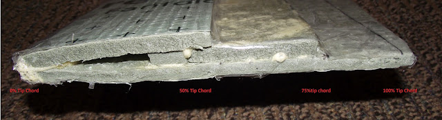
The first thing that i needed was 1/4in FFF (Fan Fold Foam) as this is the basis for the entire plane. You can either get it in huge fan folded pieces at Menards/Home Depot etc for 40$ (outrageous) or you can just get a few sheets from someone (like a contractor for a few bucks). The only thing that isnt foam are things such as the electronics, motor mount, landing gear, surface hinges etc. Most FFF is pink and has a thin plastic film on each side, but mine was a bit different: it had a plastic film on one side and a plastic film with a metal film on the other. Metal is great at blocking RF so the metal obviously has to come off. I left the other side of the FFF on(only plsatic film) because that adds a nice smoothh finish and a more sturdy foam with little weight. below you can see the orioginal foam on both sides and then it being pulled off.

Metal film side.

Plastic film side (some was peeled off).

Bare foam under metal film.

The easiest way to pull it off is to pick at a bit on the corner (very easy), and then pull it off at a 90deg angle (this way it doesn't rip like the 4th picture).

All sheets with metal film peeled off and stacked up.
Next, I downlaoded and printed off the BB42 tiled plans from here, and figured out the dimensions of the wing. I did this because: tracing isnt very accurate, im making a one piece wing, and third i wanted to learn more abount root/tip chords etc stuff about the wing. Below is a simple diagram that gives all dimensions to make the base of the wing.
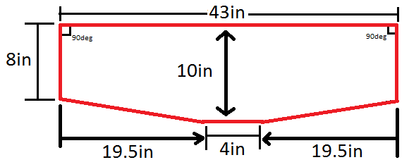

Marked the foam with a pen, tape measure, and a big "T square" to go 90deg off the sides and draw the long straight lines.

Done cutting, started to mark the lines for the kmF3 pieces. I was still trying to figure out how to do the KFm3 stuff (50 and 75% strips) so that's why there are a quite a few lines. All you need is a line at the 75% and 50% of the tip chord that goes to the opposite tip. Note that from now on, the wing must have its skin (plastic film) side down so that when it is done, the rougher, but glueable foam is inside.
Then I cut a 43in wide by 4in deep piece of FFF for the 50% strip and a 43in by 3in piece for the 75% strip.

I put a 45deg chamfer on the leading edge of the wing and on the long edge of the 50% strip.

Pretty Straight!

Then i put them together to make sure they make a nice 90deg angle.

I glued on the 75% strip so that the trailing edge of the 75% piece was at the 75% mark of the wing tip with gorilla quick PU glue.

This is where it gets more complicated. As i was doing a more aerobatic wing with polyhedral, the dowel( or CF rod etc) that supports the leading edge of the wing couldn't go the whole way or else i couldn't change the wing later for the tips of the wing that angle up (polyhedral). Since I needed 7in polyhedral tips on each side of the wing, i made two 7in long dowels and one 29in dowel (centered) which is 43 all the way across and i can still make the changes for the poly later.

I put a ~43in piece of packaging tape on the work area and then set the leading edge of the wing on about 1/3 of it. That gave me enough room to put the dowels in there. Then i set the 50% strip on the rest of the tape after the dowels, made sure it was firm. In this pic i have flipped it over and was smoothing out the tape.

and then folded it over and glued it to the 75% strip with gorilla quick PU glue.

TeDa! a 43" KFm3 wing.

I measured 7in from the tip of the wing, made a line all the way from the leading to trailing edge with a T square, ant then marked 1/8in from the 7in line on both sides. Then i took a fine toothed hand saw and made so that the two lines 1.4in apart intersected at the top of the bottom layer of foam. ( make a tiny little v in the bottom sheet of foam from the 75 to 100% chord, and then put one piece of 20in+ duck tape on the back of the wing so that most of its sticks out.

Measure from the tip of the bottom of the wing to the surface the wing is sitting on. for a 42: with 7in polys, it should be 2 1/4in (actually 2 1/8in but we go over so that when it settles the poly will not be too low). Scrape off the plastic film where the duct tape will go so that it has a good bond to the foam.

Get the inside of the v wet and squeeze some PU in there(don't be skimpy) and also a bit on the outside of the v. The wrap the duck tape back around and over the top of the wing. As it dries, the PU will bubble up a bit, so, check it every few minutes and push on the tape to get the glue back down in there. I used the same roll of duct tape to hold the wing at 2 1/4 in.

Do the same for the other side and your'e all done with a KFm3 polyhedral wing!

Printed out the sheets for the elevator from the PDF and cut them from FFF. The chamfered them to 45deg like the wing on the non-skin side.

This is how to do packaging tape hinges! Put the elevator surface on top of the hstab so that it forms a 30deg(?) angle. Put a few sheets of paper between them for space.

Then, put some tape from the surface to the hstab so that it creates a hinge (around the 30deg angle). Make sure that the two pieces are flat against each other.
Then, lay the hstab flat and put some tape across there too. you should now have a fairly easy to move control surface.

Obviously, this is the fuselage. The big thing is that i went with a full monoblock design which is hevier but way stronger thatn using a standard monoblock and FFF for the rest of the fuselage. I simply used the 3 pages spliced together from the BB43in tiled pdf of the side panels for the fuelage to cut the shape using a band saw. I stacked a three rectangles of foam on top of each other(one 2in, and two FFF pecies) that could all fit the side panel on them and cut them all at once.

Made a little motor mount cutout at the front.

Used 1 in wood bit to cut out battery, servo and RX compartments.

This is VERY VERY important for any plane newb to understand! Guess how i know! You can see the washers on the x mount of the motor, right? Those washers point the motor down and to the right 2 deg each from the cockpit view. that is so that the motor counteracts its own spinning torque. Note: I have the wrong prop on in this picture (a CCW); just haven't changed it yet.

Back view. Simple 1/8in ply with holes in it.

Covered up x mount bolts to protect them from glue. Shows how dowels go into motor mount and fuselage.

Glued all the dowels into the motor mount plywood and then glued them into the foam.

hstab and vstab done.

Hot glued onto the fuselage.

I PU glued the FFF fuselage side panels onto the 2in full fuselage (i should have done this before the hstab and vstab were on! hah). I put in the 18A SS ESC, 20-22L w/10x4.5 prop, RX and battery in there to test it.

You can also see here that i put in the dowels for mounting the wing. i put them ~<1in back and down from the leading edge (and opposite for the trailing).

Got tired of waiting so i bought a control rod kit from my LHS (total ripoff). Still using my HK 9g servos.

And also a ruder/elevator control rod kit.

I mounted the rudder/elevator servos ~1in above the hstab and in the servo "pocket" towards the back of the 1-piece-fuse so that the servo arm can never go lower than the hstab (would get caught if it did).

The servo pocket. Didn't really know how i was going to mount the servos when i started, so this may be filled or something.


Control Surface Install how-to:
1. Put a control horn on the surface so that the hole in which the control rod goes into is parallel to the center of the hinge, and it is near the center of the surface (be careful for two surfaces colliding).
2. Attach the Micro E/Z Link (aka clevis) on to the end of the Control Rod.
3. The Control Rod should be at least the distance to the servo so that you can make adjustments and have a plastic sleeve on it to route the wire to the surface from the servo.
4. Connect the servos to the RX and turn on your TX. Make sure that all channels are centered with no trim etc.
5. This should be done while the TX sticks are centered so that the servo is centered. Move the servo arm on the servo (dont just turn the servo, move the arm from the gears) so that it is either pointed straight up or straight down (or close as possible). Tighten down the arm with the little screw to the servo after powering down so you don't strip the servo.
6. Hold the surface parallel to its stabilizer (ex rudder to vstab) and mark the wire about 1in past the servo. Cut it and also cut the sleeve ~3in shorter than this.
7. Install the E/Z connector onto the servo arm. place the little aluminum piece on the outside of the arm and then push the rubber grip onto the aluminum piece on the inside of the arm.
8. Make sure the servo is centered, hold the surface parallel to the stabilizer slide the wire into the E/Z Connector and tighten it down.
9. Use hot glue or something to hold down the sleeve to something sturdy.
10. Test! should be pretty close to perfect. may have to change trim some.

The elevator surface.

I put the battery in there (not actual flight position) and tested the ruder and elevator surfaces.

Total crap landing gear made from .078in music wire, pink foam, duct tape and pen tube for a bearing. I need to bridge the gap between the wire and the tube somehow and it would be better. This thing definitely has enough power for takeoff so ill see how it does. If it works well then ill leave it (i dont care about looks on this build).

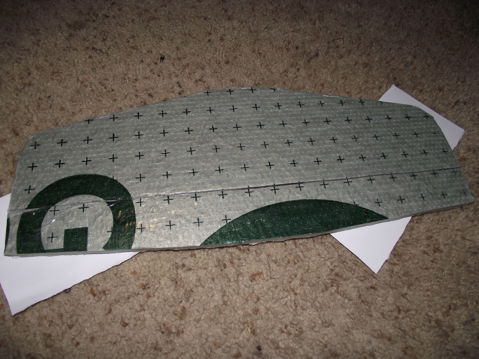
This is the finished wing except for the control horns. This can't be seen in any of the images really, but there is a dowel embedded at the center, trailing edge of the wing so that the rubber bands don't gouge the wing.

To make the custom ailerons:
1. I found the shortest 75->100% area on the wing and then made the aileron less than that (~1.5in).
2. In terms of length, i made the ailerons go 2in from the polyhedral and 2.5in from the center of the wing (so i have room for the rubber bands).
3. Then I used a tape measure to mark all of these points and then used a T-square to connect the dots.
4. I cut them out with an exacto and cut the 45 deg angles on the edge like i did for the rudder and elevator.
5. I used the same tape method to create a hinge.

I used bigger servos here because i didnt have any other ones and because these surfaces are bigger than the 32in BB. I thought that keeping them toward the center of the wing would be the best, so they are 4in from the center and 4in from the aileron surface hinge. Also, i made sure that they are inside the 50-75% step of foam so that they wont stick out of the top of the wing as they are ~.375in thick. To do the actual mount i just traced it onto the foam, cut it out, put some hot glue at the bottom, and put a piece of packaging tape over the top.


I have been doing test flights, but the first few haven't worked too well:
http://www.youtube.com/watch?v=ddBOsy0hlJ0
http://www.youtube.com/watch?v=XG63NVOVU7c
i have been talking with the people on RCG, so i hope i can get it sorted out soon!!