Wednesday, December 26, 2012

DIY USB to TTL with Nokia CA-42

I don't know exactly how, but i came across this page that went through the process. Basically, the idea is to take an old Nokia phone USB adapter and use its serial TX/RX lines as a FTDI device for MCUs or any thing that uses TTL. I found one on ebay here (USA, Buy it now) and awaited for its arrival. After it sat in the local Post Office for a day because a snowplow took out our mail box (thanks dude), i finally got it.


The Build

The guide said to solder on wires to the serial push pins of the phone connector. But, i didn't like the possibly skimpy connections and the bulkiness of the connector, so, i cut off the rubber case and planned to solder male pins directly to the wires. To my surprise there were only three wires connected on the end of the cable (green, blue and white). Weird, there should be at five: TX, RX, VCC, GND, and DTR. I then found  the image below. Without taking off the rubber case i wouldn't have known that  those wires are missing and therefore little level shifter from the guide wouldn't worked. Green and white are serial and blue is ground, but what about  VCC and DTR? FTDI isn't much use without them.


I thought that the other wires might have been left out as a clone and hoped that they would be on the PCB with the USB plug. Luckily, the case was just plastic pins press fit into some plastic receptors. AKA, i could just pry apart the case, and not have to cut it apart like the phone side. The pads for DTR and VCC are on the PCB, yay! And labels too! But, gets better: VCC is 5v unlike in the image above and the guide, so im hoping that TX/RX are also 5v so that i don't have to do 3.3v -> 5v level shifting. If the chip in the Nokia phone that uses this adapter is 5v tolerant, then that is why only gnd, rx and tx are broken out to the connector.

With two more pins, i had to replace the stock cable. I found some ribbon cable in my scrap bin (from an old rear projection TV). I simply peeled off five lines, soldered them onto the board, and soldered 5 breadboard pins onto the other side. I followed a modified FTDI scheme as this serial converter doesn't have CTS. It went like so: DTR, RX, TX, VCC, GND. Regular FTDI is RTS, RX, TX, VCC, CTS, GND. Finally, I finished them up with hot glue.


Testing

Since i already had the arduino IDE installed, i used that to test the serial adapter. To do this i connected the TX and RX lines together which essentially just sends back what you sent (make sure if you dont use Arduino IDE, that the "display what you send" feature isnt on). If it works you will  receive back what you typed. You might want to do this earlier on, or periodically throughout.

The final test: Arduino. It works with no level shifter! i uploaded the blink sketch with the Arduino IDE in Ubuntu (linux). The DTR ( auto reset on code upload) doesnt work, but pressing reset when "Binary sketch size:" appears works just fine for now!

Conclusion

If you're comfortable with a little soldering then this is a great cheapo DIY FTDI. One last note: if you get a CA-42 that has all the wires like the one in the guide and the second pic, you will have to do some level shifting.

Tuesday, December 11, 2012

Quad Booting Windows 7/8, OS X, and Ubuntu on a PC

The goal of this is to quad boot all four of these OSes on my computer. Ill start off a few months ago. The main reason I re-installed Windows 7 on my computer was because of the various programs i didnt need, leftovers in the registry, and the general slow down over time. I started off with a clean install of windows 7 and then installed all of my programs etc. Last, i made an image of it so that if anything were to go wrong in the future, i could simply restore the image without worrying about losing data, or having to re-install all of my programs. I used UBCD4WIN and is Image for Windows program.

Just a few weeks ago my computer became very laggy and ran the CPU cores up to 100% when the Task Manager wasn't running. This was an obvious sign a of a virus. I first though of simply restoring the image i made, but that would be no fun, of course! I decided to quad boot Windows 7, Windows 8, Ubuntu and OSX. Win7 is what i mainly use, I dumped Win8 a while back because the driver support was crap, and Ubuntu and OS X are for fun and what i will mainly use now because they are less prone to viruses.

Now, enough filler; onto the "meat".  The first thing i considered was the MBR format's limitation on partitions. Most would think that since its a quad boot and MBR supports a max of four primary partitions (primary are the only ones you can install OSes on), that it would work fine. Wrong! Windows installs another partition called "System Reserve" that contains a start-up fixer if windows doesn't start up properly (this is also Primary). There are ways to get around it, but i decided to simply choose a entirely different route.

Another format is called GPT. This will replace MBR because it has:
-An infinite amount of Primary partitions for OSes or data.
-A max hard drive size of 9.4 ZB (That is 9.4 Zetabytes = 9.4 BILLION Terrabytes). With 3TB HDDs  already being sold, and most computers not compatible with GPT this creates a disaster for us techies who want 2 or more TB on one drive. 2TB is the max MBR HDD size and you can still use 2TB+ HDDs on non supporting OSes, but you will only see 2TB.
 
To get my quad boot working i had to choose the GPT format. and as i said above, most computers don't have a GPT supporting OS, including mine. But there is a workaround: HybridMBR. This shows a legacy MBR to Windows 7 and others that dont support GPT, while still having all of the GPT pros and working with GPT native OSes. That being said, i couldve simply installed Windows 8 as it has GPT support, but then i would miss some drivers (Arduino, PPJOY) that Win8 doesn't support. In my quad boot Windows 7 is the "trouble causer". Ubuntu, OS X, and Win8 support GPT.

Here is how the process went. All of it is based upon this site. Thank him a ton!!!
1. Backup all data, or in my case i have the image.
2. Grab Ubuntu from here and burn it to a CD or make a liveUSB (ill do that in another post :)).
3. Go to gparted, delete all the partitions, make the HDD to GPT.
4. Create your partitions. Mine went like so:
---A) 1MB ext2 partition with bios_grub flag. REQUIRED!
---B) 250GB Windows 7 partition. Formatted to ntfs.
---C) 75GB Windows 8 Partition. ntfs.
---D) 75GB Ubuntu partition. ext4.
---E) 75GB OS X partition. Unallocated.
---F) The rest is a data partition formatted to ntfs as it is the easiest to r/w in all of my OSes.
5. Go to terminal and type sudo apt-get install gptsync.
6. Run gptsync /dev/sda2 in terminal and allow it to sync the partitions. This is the HybridMBR being made. sda2 is the HDD i made all of the partitions on in step 4. look at gparted to find this.
7. Install Windows 7 and 8 / restore the image.
8. Install OSX86.
9. Install the Chameleon bootloader. The one to rule them all (LOTR reference :D). This loader will detect all of the OSes and allow you to choose any of them.

Interfacing a PlayStation 2 (PS2) Controller with Arduino

I got a free PS2 controller, but with no PS2 to use it with I had to do SOMETHING with it, haha. That, of course, was taking it apart and using it with an Arduino as a control system.

Here is the inside:


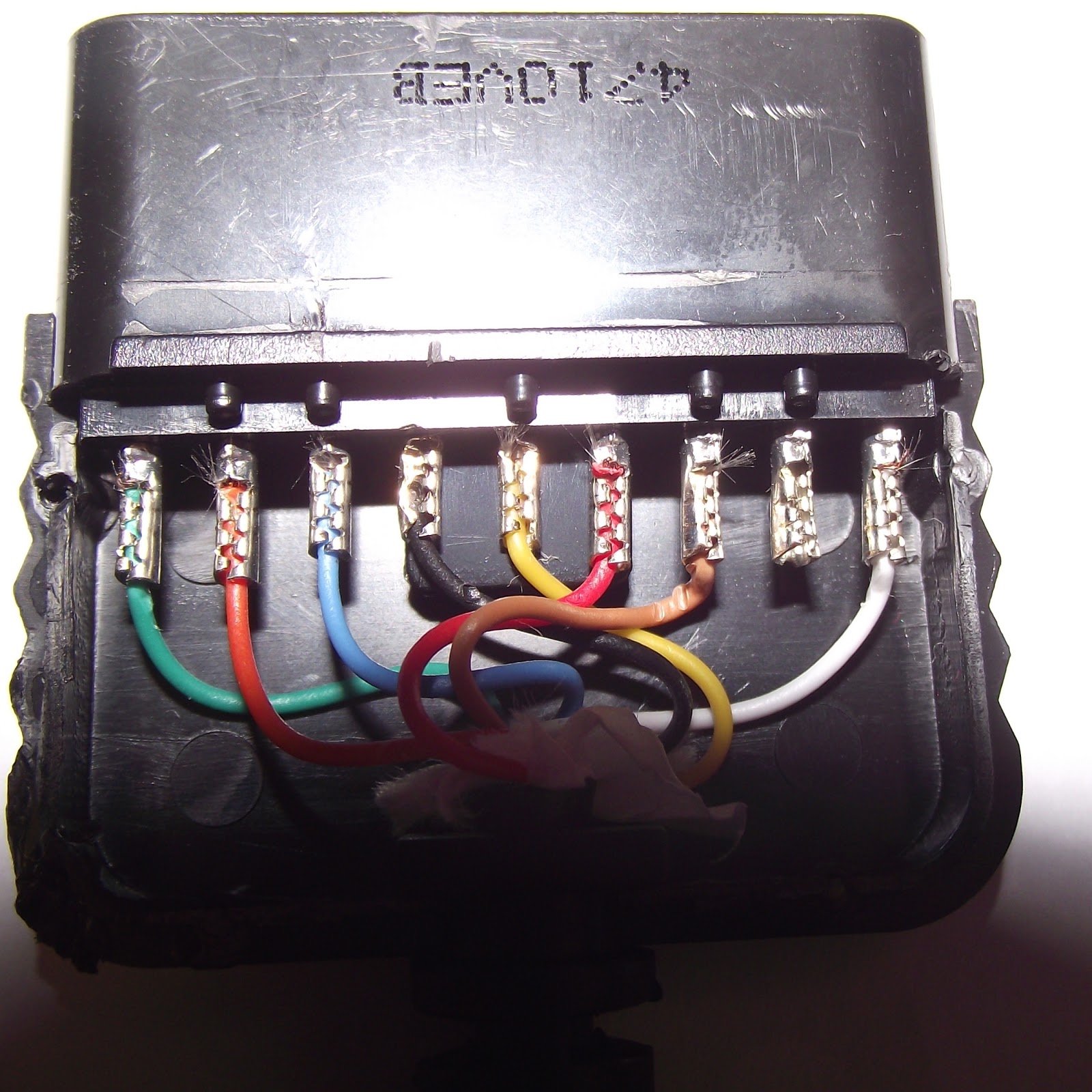
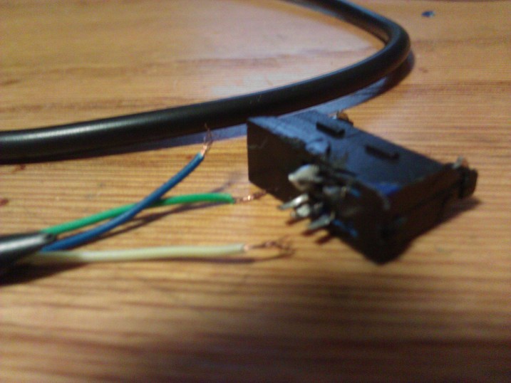
Inside the connector:


Pinout Inside Controller 


Pinout of the connector:

You can see on the PCB which wires are for each pin. Then where the wires go on the connector.

Connections to Arduino:

These are using the PSX code below. they can be changed in code.
Arduino, PS2 PCB Label, Full Name, Color
13,,,,,,,,,, CLK,,,,,,,,,,,,,,,,, (Clock),,,,,,, Brown
11,,,,,,,,,, DO,,,,,,,,,,,,,,,,,,, (Command), Orange
10,,,,,,,,,, CS,,,,,,,,,,,,,,,,,,,, (Attention),,, Red
12,,,,,,,,,, DI,,,,,,,,,,,,,,,,,,,,, (Data),,,,,,,,,, Green
GND,,,,, GND,,,,,,,,,,,,,,,, (Ground),,,,,, Black
N/C,,,,,,,,ACK,,,,,,,,,,,, (Acknowledge),, White
3.3V,,,,,,,3.3v,,,,,,,,,,,,,,,,,, (3.3v),,,,,,,,,,, Yellow
7.5V,,,,,,,See Below,,,,,,,, See Below,,, Blue

7.5v triggers the feedback motor inside of the controller. Too use this you will have to use a digital pin to trigger a mosfet/transistor to supply the 7.5v. 

Code:

Get the library from here.

#include <PS2X_lib.h>  //for v1.6

PS2X ps2x; // create PS2 Controller Class

//right now, the library does NOT support hot pluggable controllers, meaning
//you must always either restart your Arduino after you conect the controller,
//or call config_gamepad(pins) again after connecting the controller.
int error = 0;
byte type = 0;
byte vibrate = 0;

void setup(){
 Serial.begin(57600);

 //CHANGES for v1.6 HERE!!! **************PAY ATTENTION*************

 error = ps2x.config_gamepad(13,11,10,12, true, true);   //setup pins and settings:  GamePad(clock, command, attention, data, Pressures?, Rumble?) check for error

 if(error == 0){
   Serial.println("Found Controller, configured successful");
   Serial.println("Try out all the buttons, X will vibrate the controller, faster as you press harder;");
  Serial.println("holding L1 or R1 will print out the analog stick values.");
  Serial.println("Go to www.billporter.info for updates and to report bugs.");
 }
 
  else if(error == 1)
   Serial.println("No controller found, check wiring, see readme.txt to enable debug. visit www.billporter.info for troubleshooting tips");
 
  else if(error == 2)
   Serial.println("Controller found but not accepting commands. see readme.txt to enable debug. Visit www.billporter.info for troubleshooting tips");
 
  else if(error == 3)
   Serial.println("Controller refusing to enter Pressures mode, may not support it. ");
 
   //Serial.print(ps2x.Analog(1), HEX);
 
   type = ps2x.readType();
     switch(type) {
       case 0:
        Serial.println("Unknown Controller type");
       break;
       case 1:
        Serial.println("DualShock Controller Found");
       break;
       case 2:
         Serial.println("GuitarHero Controller Found");
       break;
     }

}

void loop(){
   /* You must Read Gamepad to get new values
   Read GamePad and set vibration values
   ps2x.read_gamepad(small motor on/off, larger motor strenght from 0-255)
   if you don't enable the rumble, use ps2x.read_gamepad(); with no values
 
   you should call this at least once a second
   */


 if(error == 1) //skip loop if no controller found
  return;

 if(type == 2){ //Guitar Hero Controller
 
   ps2x.read_gamepad();          //read controller
 
   if(ps2x.ButtonPressed(GREEN_FRET))
     Serial.println("Green Fret Pressed");
   if(ps2x.ButtonPressed(RED_FRET))
     Serial.println("Red Fret Pressed");
   if(ps2x.ButtonPressed(YELLOW_FRET))
     Serial.println("Yellow Fret Pressed");
   if(ps2x.ButtonPressed(BLUE_FRET))
     Serial.println("Blue Fret Pressed");
   if(ps2x.ButtonPressed(ORANGE_FRET))
     Serial.println("Orange Fret Pressed");
   

    if(ps2x.ButtonPressed(STAR_POWER))
     Serial.println("Star Power Command");
 
    if(ps2x.Button(UP_STRUM))          //will be TRUE as long as button is pressed
     Serial.println("Up Strum");
    if(ps2x.Button(DOWN_STRUM))
     Serial.println("DOWN Strum");


    if(ps2x.Button(PSB_START))                   //will be TRUE as long as button is pressed
         Serial.println("Start is being held");
    if(ps2x.Button(PSB_SELECT))
         Serial.println("Select is being held");

 
    if(ps2x.Button(ORANGE_FRET)) // print stick value IF TRUE
    {
        Serial.print("Wammy Bar Position:");
        Serial.println(ps2x.Analog(WHAMMY_BAR), DEC);
    }
 }

 else { //DualShock Controller

    ps2x.read_gamepad(false, vibrate);          //read controller and set large motor to spin at 'vibrate' speed
 
    if(ps2x.Button(PSB_START))                   //will be TRUE as long as button is pressed
         Serial.println("Start is being held");
    if(ps2x.Button(PSB_SELECT))
         Serial.println("Select is being held");
       
       
     if(ps2x.Button(PSB_PAD_UP)) {         //will be TRUE as long as button is pressed
       Serial.print("Up held this hard: ");
       Serial.println(ps2x.Analog(PSAB_PAD_UP), DEC);
      }
      if(ps2x.Button(PSB_PAD_RIGHT)){
       Serial.print("Right held this hard: ");
        Serial.println(ps2x.Analog(PSAB_PAD_RIGHT), DEC);
      }
      if(ps2x.Button(PSB_PAD_LEFT)){
       Serial.print("LEFT held this hard: ");
        Serial.println(ps2x.Analog(PSAB_PAD_LEFT), DEC);
      }
      if(ps2x.Button(PSB_PAD_DOWN)){
       Serial.print("DOWN held this hard: ");
     Serial.println(ps2x.Analog(PSAB_PAD_DOWN), DEC);
      }

 
      vibrate = ps2x.Analog(PSAB_BLUE);        //this will set the large motor vibrate speed based on
                                              //how hard you press the blue (X) button  
 
    if (ps2x.NewButtonState())               //will be TRUE if any button changes state (on to off, or off to on)
    {


        if(ps2x.Button(PSB_L3))
         Serial.println("L3 pressed");
        if(ps2x.Button(PSB_R3))
         Serial.println("R3 pressed");
        if(ps2x.Button(PSB_L2))
         Serial.println("L2 pressed");
        if(ps2x.Button(PSB_R2))
         Serial.println("R2 pressed");
        if(ps2x.Button(PSB_GREEN))
         Serial.println("Triangle pressed");
       
    }
       
 
    if(ps2x.ButtonPressed(PSB_RED))             //will be TRUE if button was JUST pressed
         Serial.println("Circle just pressed");
       
    if(ps2x.ButtonReleased(PSB_PINK))             //will be TRUE if button was JUST released
         Serial.println("Square just released");  
 
    if(ps2x.NewButtonState(PSB_BLUE))            //will be TRUE if button was JUST pressed OR released
         Serial.println("X just changed");  
 
 
    if(ps2x.Button(PSB_L1) || ps2x.Button(PSB_R1)) // print stick values if either is TRUE
    {
        Serial.print("Stick Values:");
        Serial.print(ps2x.Analog(PSS_LY), DEC); //Left stick, Y axis. Other options: LX, RY, RX
        Serial.print(",");
        Serial.print(ps2x.Analog(PSS_LX), DEC);
        Serial.print(",");
        Serial.print(ps2x.Analog(PSS_RY), DEC);
        Serial.print(",");
        Serial.println(ps2x.Analog(PSS_RX), DEC);
    }
 
 
 }


 delay(50);
   
}

LT-2115 Gateway Netbook Teardown!

This began when i thought the USB port on the left side was broken. When i tried to plug in a flash drive, it went partially in at a 35deg angle. In the end i realized that the little piece of plastic in the USB port of this laptop are fairly flexible and if a flash drive (etc) is plugged in upside down, it will sorta go in (as i mentioned before). I pretty much took it apart for no reason and wasted ~2 hours. 

Here are a few pics.
Before, at the Chameleon OS X boot loader.

Prying off the keyboard. Don't worry, the laptop was off, just a test.

Keyboard assembly off.

My tools and the top plate (track pad, keyboard, etc) off of the laptop.

Close Up of laptop in previous image. You can see the motherboard (has vga, usb and power ports) on the left. On right is connector board (more usb, audio, card reader ports). WiFi and bluetooth on bottom right-center.  The blue PCB next to the laptop is the link between the motherboard and secondary board.

The "culprit". Bottom side of motherboard. Fan, memory slot, sata etc.

As i was taking it apart, I looked for some additional ports on the motherboard that i could solder onto and more functionality (USB ports etc) like the eee pc. Sadly, i didn't find any, but found a few things left unsoldered (top left of the motherboard in this pic)

Another here: bottom left.

Shadowy close-up of the connector board!

After i put everything back together ( no extra screws :D), the keyboard didnt work! Turns out i was putting the ribbon cable in wrong. You can see in the pic above that the cable goes below the gray lock-bar, in the rest of the computer, though, the cables went above this lock-bar.

Thursday, December 6, 2012

DIY RC Hovercraft

This adventure came to be when i was doing nerdy things one day and inspired myself: "I should make a hovercraft." As a matter of fact that's pretty much how most of my projects came to be. For ex: one day on youtube a few years ago: "What?! how did i get here?(youtube is famous for having totally random "related" videos). oh, this is cool, i should make a quadcopter."

Back on topic; this project is a DIY RC hovercraft made of foam, a servo, 3s LiPo, TX/RX, 1400kz blue wonder, 9x4 prop, hot glue, zipties etc. and measures: L21xW12in. Basically, its left overs from my BB that was too big for the motor.


The Storming... 

Soooo after this great idea, i had to actually build it. That didn't happen until i came across the perfect material: EPP like foam. This stuff is fairly strong and super light so its good for RC (used a lot in planes.) Then i had to think of the shape. The EPP was in circle form with a radius of ~6.5in.

The Build 

Base Frame

I cut a bite shaped (sorry) piece out of one and made them fit together ( the incide of where the two circles meet). Now i had an oval shaped piece of foam hot glued together. Trying my best to cut straight, i took off the side curves (black lines) so that it has a front and rear "bumper". The final shape is the area in red diamonds.


Motor Mount

This part was probably the hardest part as it had to be light but still sturdy and stable. The current design consists of a 1/4 circle of foam with the motor mounted on acrylic and zipties. It tends move a little and thus bring in a lot of unwanted vibrations. Soon i think i will replace it with a balsa or something like popicle sticks. I also attempted to counter the motor torque a bit  by tilting the motor. In terms of location, it is centered by half (width) and ~3/4in back from the front.
This looks (and works) horrible and will be rebuilt with some balsa wood or Popsicle sticks etc.

Propeller Shroud 

This was simply another piece of foam traced to the outline of the propeller and then i cut a 2in larger radius circle around it for strength.


Air Cushion

I didn't really know what i was going to do for this, but i figured it was made entirely foam already, so i might as well make the cushion out of foam too. The shape was simply traced from the base and then cut out with a X-acto knife. The cushion thickness was an educated guess. i figured it could be too thin where it would crack, and not too thick where it would have too much ground resistance and weight. I decided on 1 inch.

A simple cross-section. 
Also, this its not just hot glue in there. i took some tooth pics and glued them into the bottom and then pushed the base on top to prevent shearing. Then I used some glue to seal it.

Rudder System

This is simply a 900 servo that is hot glued into the base foam sheet. It then has the servo arm mounted on it as a place to attach the cardboard rudder. This obviously didn't work well with nothing holding it on the top side. When i was finishing some other stuff for it, i was letting the hot glue gun warming up. Inspiration struck! I had the tooth pics out for the previous step so i used those as a make shift hinge! this isn't fancy as it is a bare bones DIY hovercraft, so, this worked out great. It prevented the rudder from swaying under the force of the air = mission accomplished. 


No hinge.

I thought i took a picture of it up close, but i guess not. This is all i got for it.


Lift Fans

This (these) go in the base and significantly reduce the friction between the ground and the bottom of the craft. this means faster acceleration, higher top speed, slower direction changes ( drifting!!!), more efficiency. I dont have any brushless motors fit for this task, so this part is on hold. :(

Testing

I think i should note that the thrust on this thing is crazy! Even without lift fans in the base, it zips around like crazy.

Replacing an iPod Battery

...the fun way. This adventure began a week or two ago when i washed my iPod Touch 1st Generation because I had to wash the load twice for reasons i will not say, haha. After throwing it in a bag of rice for a few days and putting some mild heat on it (evaporate the water), i got all of the water spot out of the LCD and it seemed to be dry. When i plugged it in everything worked but the WIFI. The next morning i followed my usual routine of using it with my radio mod to play music in the car. No supervised here. Once i got to school the iPod was at 20%, yikes! I figured that the water shorted the battery and ran it down too low, just like i did accidentally to one of my LiPos (did short the lipo, though :)).


A Temporary fix
For a while i just left it plugged into the car charger, but then i could hear the the engine whine in the audio because of the ground loop. this loop is caused by having the ground of the charger connected to the iPod and the ground from the radio in the audio jack. basically, its just two grounds hooked up to the same iPod. The people with those fancy speaker systems in their cars also have this issue.


Take the Back cover off
Since i cracked it open already for drying out, it was pretty easy to open up again. just take a x-acto that has a perpendicular blade (relative to the handle):
1. Get it between the little joint back case (silver) and front plate (black) on the side of the iPod.
2. Twist the knife and get it under the silver case just a bit (1/8in or less).  You should hear a little pop of the
3. Do the same all the way around (leave the dock area for last).

Warning
It is possible to damage something like this, but as long as you don't stick the knife in there to far, you wont hit anything. This area only has the battery, WiFi assembly, and the lock button exposed. that is the reason why i said 1/8in or less earlier. Everything else is under neath or covered with a metal plate.

Get the Battery Out!
After getting it open the first time i had to pull out the battery. I started out by cutting the individual wires to the battery (wouldn't want to short the + and - with a metal wire cutter). Then i carefully tried to cut the stick pads that hold the battery down with a long bladed x-acto. Did i mention try? I managed to cut open the battery: oops. If this were a lipo it probably would have went up in flames, but Li-ions are more stable and only gave off the sweet-ish lithium style lipo smell. If you smell this get it off there quick and throw it in something like sand.

Where to Get a Replacement
Then i needed a battery replacement. I could get a 6$one from ebay, but since i wanted this to be 100% DIY, i found a different battery source: flip phone batteries as these all have nearly the same style of battery If you find the right ones you can fit two of these 800mah Li-ions side by side and get 1.6 times more mah  than a regular 1000mah iPod battery. If you're lucky you could find a smartphone battery that will fit! With these phone batteries you must consider three things:

Contact pads on the battery. 
A regular phone battery has three contacts just like the iPod does. They are:
    IPod          Phone             Meaning 
1. Black             -             Negitive, GND
2. Red               +             Positiive voltage, 3.7v nominal (like a 1s LiPo)
3. White        -none-         Charging lead

The charging lead (ill call it 'c') is there to reduce the stress on the battery while charging and using the phone/ iPod at the same time. On phone batteries it is commonly the center contact and will measure the same voltage as GND to positive. See the picture below for what i mean:
Extra padding
Also in the image above you can see all of the plastic and the sticker on the actual battery. i easoly pulled it off and has a lower profile battery.

The Health of the Battery
If you are paralleling two batteries you want to make sure they are the exact same model, have a similar age and are charged to the same voltage. If you have a big voltage difference, you could end up killing a battery as the batteries would attempt to stabilize (as air pressure goes from high to low to stabilize, yeah, go AP Physics)  This would result in a large amount of current flowing that could exceed the c rate of the battery and damage it and also damage the battery that the current is flowing to. Just keep the voltages similar ;)

The Action!
Next i rigged up the new batteries to the iPod.  This was as simple as connecting the batteries in PARALLEL which keeps the same voltage, but adds the mah of the two batteries, in layman's terms. This is done for all contacts pos, neg, and c. I did this with some thinner stranded wire as it doesn't need to carry much current. I pretty much followed this:
1. Solder positive battery 1 to positive battery 2
2. Solder negative to negative
3. Solder C to C
4. Solder negative form battery 1 to the negative pad on the iPod PCB
5. Solder C from battery 1 to White (C) on the iPod PCB
6. Solder positive from battery 1 to the positive pad on the iPod PCB

Finally! Testing Time!
I pressed the button and it worked! Yay! Also, must note that from looking at a possible donor iPod Touch 2nd Generation, that flip phone batteries probably wont work because of the slimmer design.

Tuesday, December 4, 2012

Downloading and Upload Pictures via Flickr with Processing

Over the  weekend i was asked to do some processing code for someone. Basically, it involved searching by a inputted term, grabbing a few of the search results, modifying them and then a final re-upload back to Flickr. There were a few more challenging parts:
1. Grabbing the images.
2. Using PGraphics to modify them.
3. Uploading.

So i have created a simple sketch that does all of these, commented, and simple as possible so its easy to  understand. http://dl.dropbox.com/u/28052258/example_Flickr.zip

Some code snipits
1.
 if (millis() - lastTime > loopTime) //refresh images over loopTime
  {

    println("Getting images from flickr...");
    try
    {
      println(searchTerm);
      searchTerm = URLEncoder.encode(searchTerm, "UTF-8"); //encode string to UTF8
    }
    catch (Exception e) //maily for catching exceptions if string is null
    {
      e.printStackTrace();
      exit();
      return;
    }

    //create the search XML URL based on search term
    String url =  "http://api.flickr.com/services/rest/?method=flickr.photos.search&api_key=bfaa37fbd00c1291ced65b903fb15fda&text="
      + searchTerm + "&format=rest";

    //process data into XML elelment from the URL above
    processing.xml.XMLElement xml = new processing.xml.XMLElement(this, url);

    xml = xml.getChild(0);
    processing.xml.XMLElement[] photos = xml.getChildren();

    //Everything until know only needed to be run once per search term.
    //the following gets each indiividual image. so its a loop
    for (int i = 0; i < searchQuantity; i++) //run until we reach the last image wanted
    {
      processing.xml.XMLElement photo = photos[i]; //grab the specific line for photo i
      //make the URL for that specific image
      String imgURL = "http://farm" + photo.getStringAttribute("farm")
        + ".static.flickr.com/"
          + photo.getStringAttribute("server") + "/"
          + photo.getStringAttribute("id") + "_"
          + photo.getStringAttribute("secret") + "_z.jpg"; //adding _z makes the image 640x480 instead of the smaller image.

      name[i] = photo.getStringAttribute("name"); //grab name from photo and put it in the name String array

      //status message
      print("downloading " + (i+1) + "/" + searchQuantity + ":");
      //paste this into the URL bar of you browser and you wll see the image
      println(imgURL); // the URL of the actaul image.

      //the actual retrieve image command.
      FlickrPics[i] = loadImage(imgURL);//display the images with mods


      if (i < 4)
      {
        //first row
        image(FlickrPics[i], 20 + (160 * i), 20, 160, 120); //image(PImage object to display,
        //image(PImage object to display,
        //x coord of the images left corner,
        //y ---------------------right corner,
        //width to resize to,    //i just m
        //height to resize to); ade it a fourth of full size
      }
      else
      {
        //second
        image(FlickrPics[i], 20 + (160 * (i - 4)), 140, 160, 120);
      }
    }

    modifyImages();
    UploadImages(); // call the uplaod function and upload the images to flickr/save to hdd

    for (int i = 0; i < searchQuantity; i++) //update images again with new pgraphics
    {
      if (i < 4)
      {
        //first row
        image(FlickrPics[i], 20 + (160 * i), 20, 160, 120); //image(PImage object to display,
        //image(PImage object to display,
        //x coord of the images left corner,
        //y ---------------------right corner,
        //width to resize to,    //i just m
        //height to resize to); ade it a fourth of full size
      }
      else
      {
        //second
        image(FlickrPics[i], 20 + (160 * (i - 4)), 140, 160, 120);
      }
    }
  }


2.
 void modifyImages()
{
  for (int i=0; i < searchQuantity; i++) //loop through each image adding the img to it
  {
    println("modifying FlickrPics["+ i+ "]");
    PGraphics output = createGraphics(640, 480, P2D);

    //start to draw on the PGraphics
    output.beginDraw();

    output.image(FlickrPics[i], 0, 0); //640x480
    output.image(img, 0, 0); //640x480
    //both are 640x480 so ill added them both in the upper left corcner with 0,0

      output.endDraw(); //done drawing

    FlickrPics[i] = output.get(); // saves the new iamge back to the source
  }
}


3.

 void UploadImages()
{
  for (int i=0; i < searchQuantity; i++)
  {
    // First compress it as a jpeg.
    byte[] compressedImage = compressImage(FlickrPics[i]);

    // Set some meta data.
    UploadMetaData uploadMetaData = new UploadMetaData(); 
    uploadMetaData.setTitle(uploadTitle); 
    uploadMetaData.setDescription(uploadDescription);   
    uploadMetaData.setPublicFlag(true);

    String saveName = "/created/" + "Tag.Grind" + i + ".jpg";
    try
    {
      //FlickrPics[i] = 
      FlickrPics[i].save(saveName);
    }
    catch (Exception e)
    {
      println("Local Save failed");
    }

    // Finally, upload/
    try
    {
      uploader.upload(compressedImage, uploadMetaData);
      println("Picture" + " " + (i + 1) + " uploaded");
    }
    catch (Exception e)
    {
      println("Upload failed");
    }
  }
  println("Upload Complete!");
}